Signal amplification circuit and active bias circuit

A technology of signal amplifying circuit and bias circuit, which is applied to parts of amplifying devices, amplifiers, power amplifiers, etc., to achieve the effect of reducing dependence, realizing the amplification function, and reducing the starting voltage

Active Publication Date: 2020-05-26
GUANGZHOU HUIZHI MICROELECTRONICS
View PDF4 Cites 0 Cited by
  • Summary
  • Abstract
  • Description
  • Claims
  • Application Information

AI Technical Summary

Problems solved by technology

[0004] However, since the active bias circuit in the related art has two triodes connected in series, the active bias circuit needs a higher power supply voltage (Vbat) to start the normal operation of the whole circuit, but this is not necessary for mobile terminals. is an obvious limiting factor

Method used


Image

  • Signal amplification circuit and active bias circuit
  • Signal amplification circuit and active bias circuit
  • Signal amplification circuit and active bias circuit

Examples


Embodiment 1

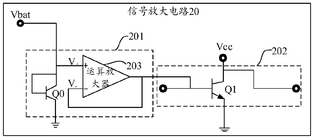
[0046] Such as figure 2 Shown is an optional circuit diagram of the signal amplifying circuit provided in the embodiment of the present application, and the signal amplifying circuit 20 includes an active bias circuit 201 and a radio frequency amplifying circuit 202 .

[0047] The active bias circuit 201 includes a first branch and a second branch connected in parallel with the first branch, the second branch includes an operational amplifier 203, and the active bias circuit 201 passes the operation Amplifier 203 outputs a bias voltage.

[0048] The first branch is formed by a first transistor Q0, and the emitter set of the first transistor Q0 is grounded. Here, the first transistor Q0 may be an NPN transistor or a PNP transistor. Taking Q0 as an NPN transistor as an example, the base and collector of the transistor Q0 in the first branch are short-circuited, and it is used as a diode in the circuit to provide the bias current output by the entire active bias circuit.

[004...

Embodiment 2

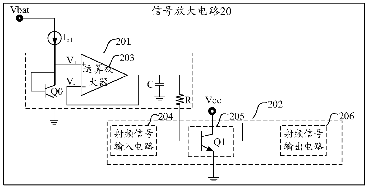
[0055] Such as image 3 Shown is another optional circuit diagram of the signal amplifying circuit provided by the embodiment of the present application. The signal amplifying circuit 20 includes an active bias circuit 201 and a radio frequency amplifying circuit 202 .

[0056] The active bias circuit 201 includes a first branch and a second branch connected in parallel with the first branch, the second branch includes an operational amplifier 203, and the active bias circuit 201 passes the operation Amplifier 203 outputs a bias voltage.

[0057] The first branch is composed of a first transistor Q0, and the emitter set of the first transistor Q0 is grounded, and the first transistor Q0 is used to realize the current output function in the bias circuit.

[0058] The second branch is used to provide a bias voltage to the RF amplifier circuit 202 .

[0059] In some embodiments, the active bias circuit 201 also includes a constant current source I b1 ; The constant current sou...

Embodiment 3

[0069] An embodiment of the present application provides a signal amplifying circuit, and the signal amplifying circuit includes an active bias circuit and a radio frequency amplifying circuit. The active bias circuit includes a first branch and a second branch connected in parallel with the first branch, the second branch includes an operational amplifier 203, and the active bias circuit outputs through the operational amplifier 203 Bias voltage; the first branch is used to realize the current output function in the bias circuit. The second branch is used to provide a bias voltage to the RF amplifier circuit 202 .

[0070] Such as Figure 4 Shown is a circuit diagram of an operational amplifier provided in the embodiment of the present application, and the operational amplifier 203 in the second branch includes a first voltage stabilizing branch 401 and a second voltage stabilizing branch 402 .

[0071] The first voltage stabilizing branch 401 includes a first transistor Q5...


PUM


Abstract

The embodiment of the invention provides a signal amplification circuit and an active bias circuit. The signal amplification circuit comprises the active bias circuit and a radio frequency amplification circuit; the active bias circuit comprises a first branch circuit and a second branch circuit connected with the first branch circuit in parallel; the second branch circuit comprises an operationalamplifier; and the active bias circuit outputs bias voltage through the operational amplifier; and the radio frequency amplification circuit is connected with the active bias circuit and is used foramplifying an input signal input into the signal amplification circuit under the action of the bias voltage. According to the invention, the dependence of the active bias circuit on the power supply voltage can be reduced, so that the starting voltage of the whole circuit is reduced; the starting work can be realized under lower power supply voltage; stable bias voltage is input into the radio frequency amplification circuit; and the amplification function of the radio frequency amplification circuit is realized.

Description

technical field [0001] This application relates to the field of circuits, involving but not limited to a signal amplification circuit and an active bias circuit. Background technique [0002] In the mobile communication system, after the radio frequency signal is input, it is amplified by the power amplifier and then output. Among them, if the amplifier composed of transistors can amplify the radio frequency signal without distortion, it must ensure that the emitter junction of the transistor is positively biased and the collector Junction reverse bias. Therefore, the signal amplifying circuit usually requires an additional bias circuit to provide appropriate voltage and current to ensure the normal amplification of the transistor. [0003] The signal amplifying circuit in the related art includes an active bias circuit and a radio frequency amplifying circuit, wherein, the active bias circuit includes two triodes connected in series and grounded and an emitter follower (Em...

Claims


Application Information

Patent Timeline
Patent Type & Authority Applications(China)
IPC IPC(8): H03F3/24H03F1/00
CPCH03F3/245H03F1/00Y02D30/70
Inventor 苏强牛旭奕江涛
Owner GUANGZHOU HUIZHI MICROELECTRONICS
Why Eureka
Try Eureka