Supercharge Your Innovation With Domain-Expert AI Agents!

An automatic stamping system

An automatic, stamping head technology, applied in the direction of safety equipment, feeding devices, manufacturing tools, etc., can solve the problems of low stamping efficiency, high production cost, injury, etc., to achieve improved stamping efficiency, low production cost, and increased danger Effect

Active Publication Date: 2021-01-19
佛山海沃汽车配件有限公司
View PDF5 Cites 0 Cited by
  • Summary
  • Abstract
  • Description
  • Claims
  • Application Information

AI Technical Summary

Problems solved by technology

[0003] In the process of realizing the present invention, the inventors found that there are at least the following problems in the prior art: stamping a part is usually done by manually putting the raw material into the stamping equipment, and the work efficiency is low. If you are not careful, you will be injured, which increases the risk of work. Although the current technology also realizes the processing of workpieces through mechanical automatic stamping, most of the loading and unloading processes need to be done manually. The work efficiency is extremely low, and the existing stamping parts need to be stamped many times. However, the existing stamping equipment needs to repeatedly loosen and clamp the parts to be stamped. The stamping efficiency is extremely low, which reduces the production efficiency of the enterprise. It cannot meet the development of the enterprise, and the structure of the existing stamping equipment is too complicated, the production cost is high, and the maintenance is difficult

Method used


Image

  • An automatic stamping system
  • An automatic stamping system
  • An automatic stamping system

Examples


Embodiment

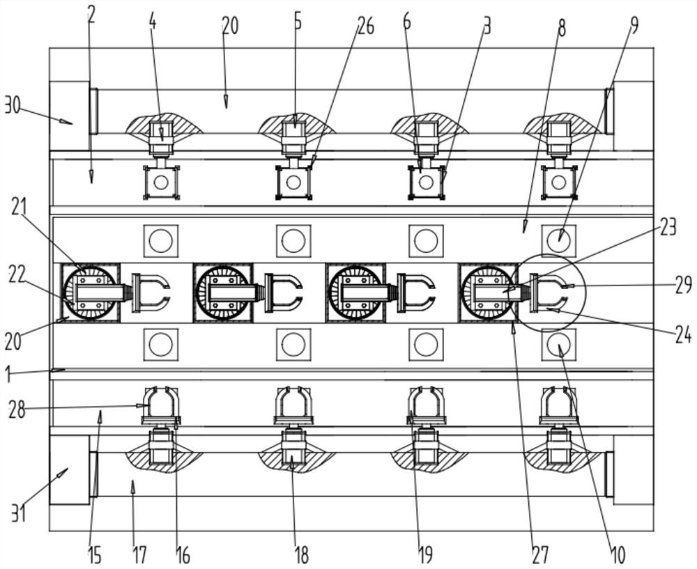
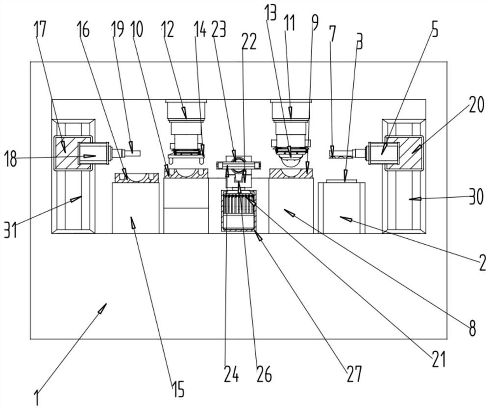
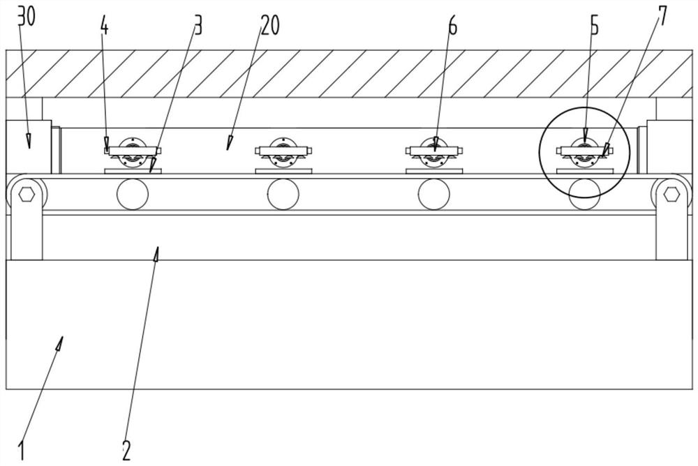
[0031] Embodiment: an automatic stamping system, comprising a body 1, on which a feeding structure, a stamping structure and a discharging structure are installed;

[0032] Please refer to the attached Figure 1-7 , in the specific implementation process, the feeding structure includes: the first conveyor 2, several fixed seats 3, two first linear module translation platforms 30, the first carrying plate 20, several first cylinders 5, Several connecting plates 6 and several vacuum suction cups 7; the connection relationship is as follows:

[0033] The first conveyor 2 is placed on the machine body 1, several fixed seats 3 are respectively placed on the first conveyor 2, two first linear module translation platforms 30 are respectively placed at both ends of the machine body 1, and the first bearing plate The two ends of 20 are respectively connected to the moving ends of the two first linear module translation stages 30, several first cylinders 5 are respectively arranged on ...


PUM


Abstract

The embodiment of the invention provides an automatic stamping system. The system comprises a machine body, wherein a feeding structure, a stamping structure and a discharging structure are installedon the machine body, the feeding structure comprises a first conveyor, a plurality of fixing bases, two first linear module translation tables, a first bearing plate, a plurality of first air cylinders, a plurality of connecting plates and a plurality of vacuum suction cups, the first conveyor is arranged on the machine body, the plurality of fixing bases are arranged on the first conveyor, the two first linear module translation tables are arranged at the two ends of the machine body correspondingly, and the two ends of the first bearing plate are connected to the moving ends of the two firstlinear module translation tables correspondingly. The automatic stamping system relates to the technical field of stamping equipment, is simple in structure, reasonable in design and low in production cost, manual adjustment, feeding and discharging are not needed, automation of stamping, feeding and discharging is achieved, the stamping efficiency is improved, and the safety performance is high.

Description

technical field [0001] The invention relates to the technical field of stamping equipment, in particular to an automatic stamping system. Background technique [0002] Stamping is a forming processing method that applies external force to plates, strips, pipes, profiles, etc. to cause plastic deformation or separation, thereby obtaining workpieces (stamping parts) of required shape and size. Compared with castings and forgings, stamping parts have the characteristics of thinness, uniformity, lightness and strength. Stamping can produce workpieces with ribs, ribs, undulations or flanges that are difficult to manufacture by other methods to increase their rigidity. [0003] In the process of realizing the present invention, the inventors found that there are at least the following problems in the prior art: stamping a part is usually done by manually putting the raw material into the stamping equipment, and the work efficiency is low. If you are not careful, you will be inju...

Claims


Application Information

Patent Timeline
Patent Type & Authority Patents(China)
IPC IPC(8): B21D22/02B21D43/18B21D45/00B21D55/00
CPCB21D22/02B21D43/18B21D45/00B21D55/00
Inventor 不公告发明人
Owner 佛山海沃汽车配件有限公司
Features
  • R&D
  • Intellectual Property
  • Life Sciences
  • Materials
  • Tech Scout
  • Unparalleled Data Quality
  • Higher Quality Content
  • 60% Fewer Hallucinations
Learn More