Welding locking and fixing device for connection point of steel structure
A technology for fixing devices and connecting points, applied in welding equipment, auxiliary devices, auxiliary welding equipment, etc., can solve the problems of welding area occupation and difficulty in meeting the welding clamping requirements of steel structures, so as to improve welding firmness and avoid occupation of steel structures. Structural welding area, easy to weld effect
- Summary
- Abstract
- Description
- Claims
- Application Information
AI Technical Summary
Problems solved by technology
Method used
Image

Examples
Embodiment 1
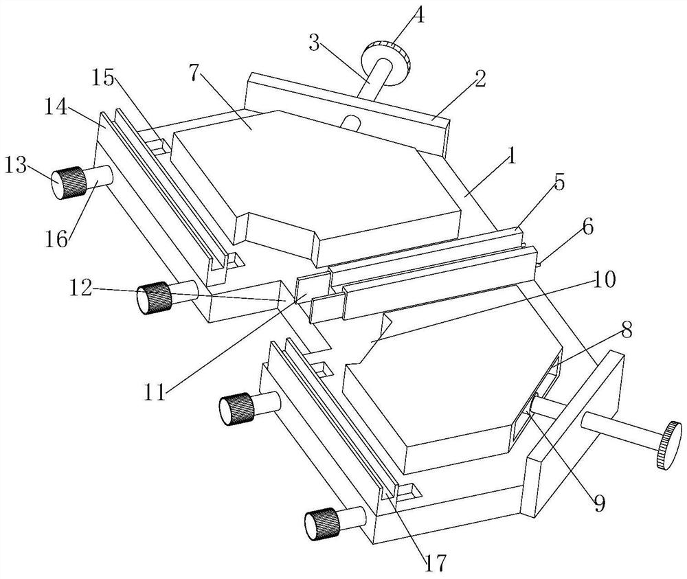
[0037] see Figure 1-5 as well as Figure 7 , is a schematic diagram of the overall structure of a steel structure connection point welding and locking fixture, a steel structure connection point welding and locking fixture, including a horizontally fixed bottom plate 1, and a square block-shaped first in the middle of the top of the bottom plate 1 A stopper 5, the front end left and right sides of the first stopper 5 are equipped with the second stopper 14, be fixed at right angle between the first stopper 5 and the second stopper 14, the front end of the first stopper 5 and be positioned at two The middle part of the second stop block 14 on the side is provided with a relief opening 12, and the relief opening 12 is a U-shaped structure, and top blocks 7 are symmetrically installed on the left and right sides of the first block 5, and the top block 7 is a pentagonal structure. Two of the side walls of the block 7 are parallel to the first block 5 and the second block 14, the...
Embodiment 2
[0042] see Figure 1-6 , is a schematic diagram of the overall structure of another steel structure connection point welding locking fixture. This embodiment has similarities with the above-mentioned embodiment 1, and the similarities will not be described in this embodiment. The specific differences are:
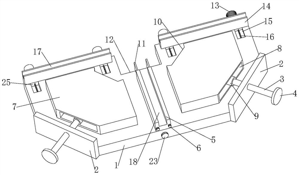
[0043] The middle part of the top of the bottom plate 1 is provided with a linear second guide groove 21, the second guide groove 21 is perpendicular to the second stopper 14 on both sides, the opening of the second guide groove 21 faces upward, and the middle part of the second guide groove 21 is installed There is a third adjusting screw rod 24, the top of the third adjusting screw rod 24 stretches through the base plate 1 to the rear end of the base plate 1; a third adjusting knob 23 is installed on the top of the third adjusting screw rod 24 stretching out at the rear end of the base plate 1;
[0044] The bottom end of the first block 5 is fixed with a square block-shap...
Embodiment 3
[0049] see Figure 1-5 as well as Figure 8 , is a schematic diagram of the overall structure of another steel structure connection point welding locking fixture. This embodiment has similarities with the above-mentioned embodiment 1, and the similarities will not be described in this embodiment. The specific differences are:
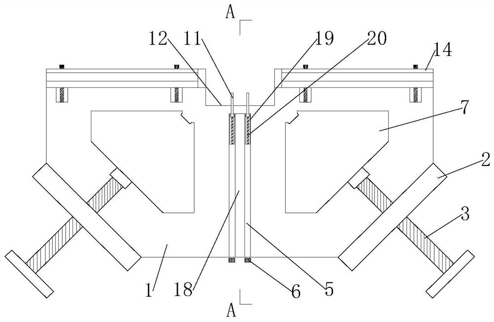
[0050] The top of the first block 5 is provided with a second slot 18 of U-shaped structure; and the opening of the second slot 18 faces upward, and the top of the second block 14 is provided with a first slot 17 of U-shaped structure, and The opening of the first card slot 17 faces upward.
[0051] When the three steel structures are T-shaped spot welded, the present invention provides a second draw-in groove 18 with a U-shaped structure at the top of the first block 5, and a first slot with a U-shaped structure at the top of the second block 14. The slot 17 makes the three steel structures respectively placed in the slots at the tops of the three st...
PUM
 Abstract
Description
Claims
Application Information
 - R&D
- Intellectual Property
- Life Sciences
- Materials
- Tech Scout
- Unparalleled Data Quality
- Higher Quality Content
- 60% Fewer Hallucinations
Browse by: Latest US Patents, China's latest patents, Technical Efficacy Thesaurus, Application Domain, Technology Topic, Popular Technical Reports.
© 2025 PatSnap. All rights reserved.Legal|Privacy policy|Modern Slavery Act Transparency Statement|Sitemap|About US| Contact US: help@patsnap.com