
An automatic and fast chip removal device and chip removal method for numerical control processing tools

A tool and automatic technology, applied in the direction of manufacturing tools, metal processing equipment, metal processing machinery parts, etc., can solve the problem of inaccurate working position of chip removal of CNC machining tools, inconvenience of moving and adjusting the position of work, and suitable range of chip removal device. minor issues

Active Publication Date: 2021-04-09
正德职业技术学院
View PDF12 Cites 0 Cited by
  • Summary
  • Abstract
  • Description
  • Claims
  • Application Information

AI Technical Summary

Problems solved by technology

[0004] The purpose of the present invention is to solve the inconvenience of moving and adjusting the position of the existing chip removal device for CNC machining tools. The efficiency is very slow; the device itself is not easy to repair and maintain; the existing chip removal device can only be adapted to the CNC machining tools of the same volume, height, and shape for chip removal work, and the adaptation range of the chip removal device is small; The area covered by the chip removal device for the chip blowing and chip removal work of CNC machining tools is too small and the coverage is not comprehensive; the chip removal device is not thorough for the chip removal of CNC tool tools, and a kind of automatic and rapid chip removal for CNC tool tools is proposed Device and method for removing dandruff

Method used


Image

  • An automatic and fast chip removal device and chip removal method for numerical control processing tools
  • An automatic and fast chip removal device and chip removal method for numerical control processing tools
  • An automatic and fast chip removal device and chip removal method for numerical control processing tools

Examples


Embodiment Construction

[0030] The technical solutions of the present invention will be clearly and completely described below in conjunction with the embodiments. Apparently, the described embodiments are only some of the embodiments of the present invention, not all of them. Based on the embodiments of the present invention, all other embodiments obtained by persons of ordinary skill in the art without creative efforts fall within the protection scope of the present invention.

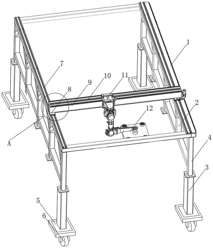
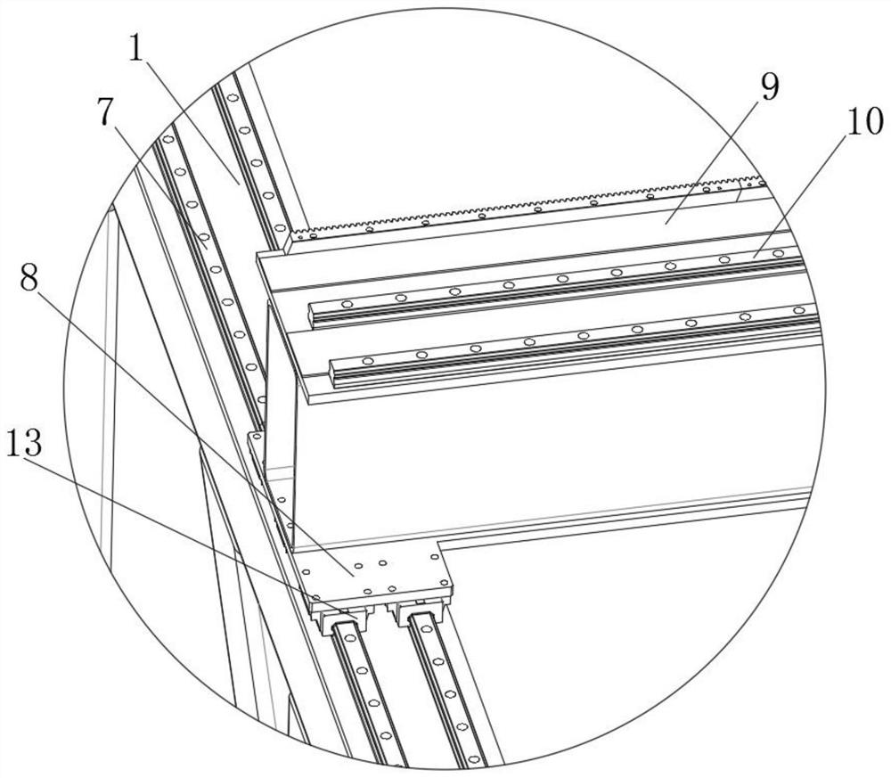
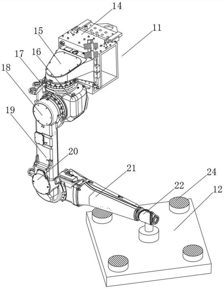
[0031] see Figure 1-5 As shown, an automatic fast chip removal device for CNC machining tools, including a hollow cuboid-shaped top connecting platform 1, four hydraulic cylinders 3, an upper hanging rod 9 and a transfer mechanism 11, and the bottom of the four corners of the top connecting platform 1 Hydraulic cylinders 3 are arranged vertically, and hydraulic rods 4 are stretched above the four hydraulic cylinders 3, and the four hydraulic rods 4 are respectively vertically connected to the bottom of the four corners of ...


PUM


Abstract

The invention discloses an automatic fast chip removal device for numerical control processing tools, which comprises a hollow cuboid-shaped top connecting platform, four hydraulic cylinders, upper hanging rods and a transfer mechanism, and the four corners of the top connecting platform are all vertical A hydraulic cylinder is arranged to the direction, and a hydraulic rod is connected to extend above the four hydraulic cylinders. The beneficial effects of the present invention are: the six motors on the hanging frame drive the gears to roll on the two side walls of the roller rails to drive the lower connecting plate to adjust left and right, move the lower connecting plate to the top of the numerical control processing tool, and set the lower connecting plate in the upper direction The four blowers of the machine blow air synchronously to blow and remove chips on the processing table on the data processing tool to keep the surface of the CNC processing tool clean, and the hydraulic cylinder drives the top connecting table to move up and down to ensure that the device can adapt to different heights. The CNC machining tools perform chip removal work, and the six motors drive the disc to move left and right, ensuring that the device can perform chip blowing and chip removal work on CNC processing tools of different sizes and shapes more accurately and appropriately.

Description

technical field [0001] The invention relates to a chip removal device, in particular to an automatic and fast chip removal device and a chip removal method for numerically controlled machining tools, belonging to the technical field of chip removal devices. Background technique [0002] During the CNC machining process of CNC machining tools, it is necessary to periodically blow and remove chips on the surface of CNC machining tools through the chip removal device, so as to ensure the cleanliness of the surface of the CNC machining tools and the quality of the processed objects. [0003] Existing chip removal devices for numerical control processing tools still have many deficiencies in use. The existing chip removal devices for numerical control processing tools are very inconvenient to move and adjust the working position. The position of the chip work is not accurate, and the efficiency of chip removal for CNC machining tools is also very slow. The device itself is not ea...

Claims


Application Information

Patent Timeline
Patent Type & Authority Patents(China)
IPC IPC(8): B23Q11/00
CPCB23Q11/005
Inventor 龚君赵寿宽
Owner 正德职业技术学院
Learn More