Siphon pipe end part structure for steam-head roller

A technology for end structures and siphons, applied in siphons, machining/deformation, machines/engines, etc., can solve problems such as difficult precision machining, unreliability, and inseparable technical guidance

Pending Publication Date: 2020-05-29
抚顺东旭精工制辊科技有限公司
View PDF0 Cites 1 Cited by
  • Summary
  • Abstract
  • Description
  • Claims
  • Application Information

AI Technical Summary

Problems solved by technology

[0008] The most common condensate siphon system for 
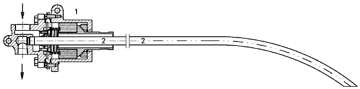
steam heating rollers mainly includes two parts: a rotary joint and a siphon pipe. It can be directly installed on the end of the roller, or can be installed on the end of the roller through the threaded connection hole processed at the end of the shaft head, or can be installed on the end of the roller through a flange; the siphon is usually made of ordinary steel pipe, The front end is formed into an elbow by progressive bending, and the end is installed on the rotary joint by screw fastening; the traditional elbow condensate siphon system has always been, and even today, still the most common and most commonly used condensate water system in the market The advantages of the siphon system are: the siphon is usually made of ordinary steel pipe, which is simple to process, easy to manufacture, low in cost, easy to install and disassemble, and can meet or basically meet the needs of corrugating machines, and even most corrugating machines at present; the disadvantages are:
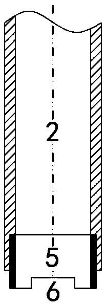
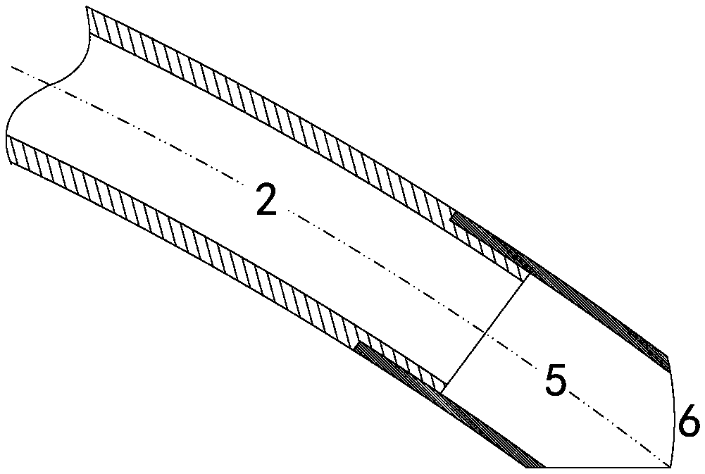
It is worth noting that: the siphon tube is limited by material selection, length and diameter, and it is difficult to perform precision machining except for the thread at the end of the installation;
[0010] 2. It is impossible to ensure the siphon gap accurately, reliably and controllably
The traditional elbow type siphon is only installed at the end of the swivel joint or the end cap of the swivel joint without any other supporting structure. Due to the limitation of its length, weight, simple support beam mode and rigidity, it cannot be in the ideal design position at all. In addition to the complex site and actual external factors, the common symptoms are: when the roller is running slowly, the sound of the siphon scraping cavity is often heard. The reason is that the siphon lacks an effective second support positioning structure;
[0011] 3. The vertical position of the elbow cannot be guaranteed reliably, controllably and effectively
[0014] The advantages of the traditional elbow condensate siphon system are simple structure, easy processing, easy installation and disassembly, and low cost; the disadvantages are uncontrollable, unreliable, unstable, and imprecise, and it is impossible to control the gap between the elbow and the roller cavity, and it is impossible to control The specific position of the elbow
The advantages of the controllable or effective condensate siphon system are: controllable, reliable, stable and precise, it can precisely control the gap between the elbow and the roll cavity, and discharge condensate efficiently; it can effectively lock and control the position of the elbow, without rollers" "banana effect"; the disadvantages are: complex structure, high processing and manufacturing costs, difficult installation and disassembly, inseparable from the necessary technical guidance, and even inseparable from special installation and disassembly tools
[0018] In summary, the external factors for the breakage of the siphon tube or the head of the siphon tube are the fatigue fracture caused by the impact of the high-speed running roller for a long time without interruption. There are two general directions for the solution of the problem, one is to increase the size of the siphon tube Self-strength, but its temporary solution does not cure the root cause. Even the one-piece siphon can be impacted to fatigue fracture, and then take a step back. If the siphon is strong enough, it is the turn of the rotary joint or the support sleeve to break; the second is to increase the size of the siphon. The design gap, the siphon tube will not be broken due to the impact of external force, but this will cause another bigger problem, the design gap is large, the water ring generated when the roller is running is thickened, and the heat conduction efficiency of the roller is low. The "banana effect" of the roller appears, which is a technical dilemma

Method used


Image

  • Siphon pipe end part structure for steam-head roller
  • Siphon pipe end part structure for steam-head roller
  • Siphon pipe end part structure for steam-head roller

Examples


Embodiment approach ( 1

[0033] Preferred implementation mode (1): suitable for bent pipe siphon: 1. Design the siphon gap of the siphon to be 10-15mm; 2. Design the protective end of the siphon, including but not limited to material, structure, connection and fixing method, etc., so that the protective end The siphon gap at the top is 2mm, and the specifications and forms of the horizontal opening at the end of the protection are designed; 3. According to the design drawings and technical requirements, manufacture or purchase acceptance.

Embodiment approach ( 2

[0034] Preferred embodiment (2): suitable for straight pipe siphon: 1. Design the siphon gap of the siphon to be 5-10mm; 2. Design the protective end of the siphon, including but not limited to material, structure, connection and fixing method, etc., so that the protective end The siphon gap at the top is 2mm, and the specifications and forms of the horizontal opening at the end of the protection are designed; 3. According to the design drawings and technical requirements, manufacture or purchase acceptance.


PUM


Abstract

The invention discloses a siphon pipe end part structure for a steam-head roller, belongs to the mechanical field, and primarily relates to the siphon pipe end part structure for the steam-head roller. The structure is characterized in that a siphon pipe is provided with a protecting end part. Minimization and effectiveness of a siphon gap are guaranteed through the protecting end part by enlarging the siphon gap of the siphon pipe in terms of principles of couple hardness with softness and Yin and Yang assisting each other: the siphon pipe is easy to break if too rigid and the siphon pipe isnot rigid persistently, the siphon pipe is easy to bend if too flexible and the flexibility is not persisted, and it is bound to loss and Yin is lost to benefit Yang. Impact of the roller is absorbedand avoided by means of elastic deformation, flexible deformation and quick wear of the protecting end part, so that a technical problem in a dilemma that it is to guarantee the minimum siphon gap ofthe siphon pipe and it is to guarantee that the guarantee pipe is free of fatigue break due to impact of the high speed operating roller is solved.

Description

technical field [0001] The invention belongs to the field of machinery, and mainly relates to the end structure of the siphon pipe of the condensed water siphon system of the steam heating roller. A shaft head is connected and fixed at each end, and one end of the shaft head extends into the roller body, and one shaft head of the roller is a through-hole structure, such as a corrugated roller and a pressure roller used for heating corrugated cardboard. The present invention is illustrated by taking the corrugated roll as the end structure of the siphon tube of the condensed water siphon system of the typical steam heating roll. Background technique [0002] Corrugated cartons are the most widely used green packaging products. The corrugated box is made of corrugated cardboard, and the corrugated cardboard is manufactured by the corrugated cardboard production line. The core of the corrugated cardboard production line is the corrugating machine. Cots, and the 5 rollers are ...

Claims


Application Information

Patent Timeline
IPC IPC(8): B31F1/20F04F10/00
CPCB31F1/20F04F10/00
Inventor 齐凤伟
Owner 抚顺东旭精工制辊科技有限公司
Why Eureka
Try Eureka