Transport type blast hole blocking structure design method

A technology for structural design and blasting holes, applied in blasting and other directions, can solve the problems of enhancing the blocking structure of blasting holes and the frictional resistance of the hole wall, the rate of large orifices, and the difficulty of blasting gas, so as to improve the energy utilization rate and reduce the hole size. The effect of increasing the blockage rate and increasing the range of action

Active Publication Date: 2020-05-29
WUHAN UNIV
View PDF10 Cites 3 Cited by
  • Summary
  • Abstract
  • Description
  • Claims
  • Application Information

AI Technical Summary

Problems solved by technology

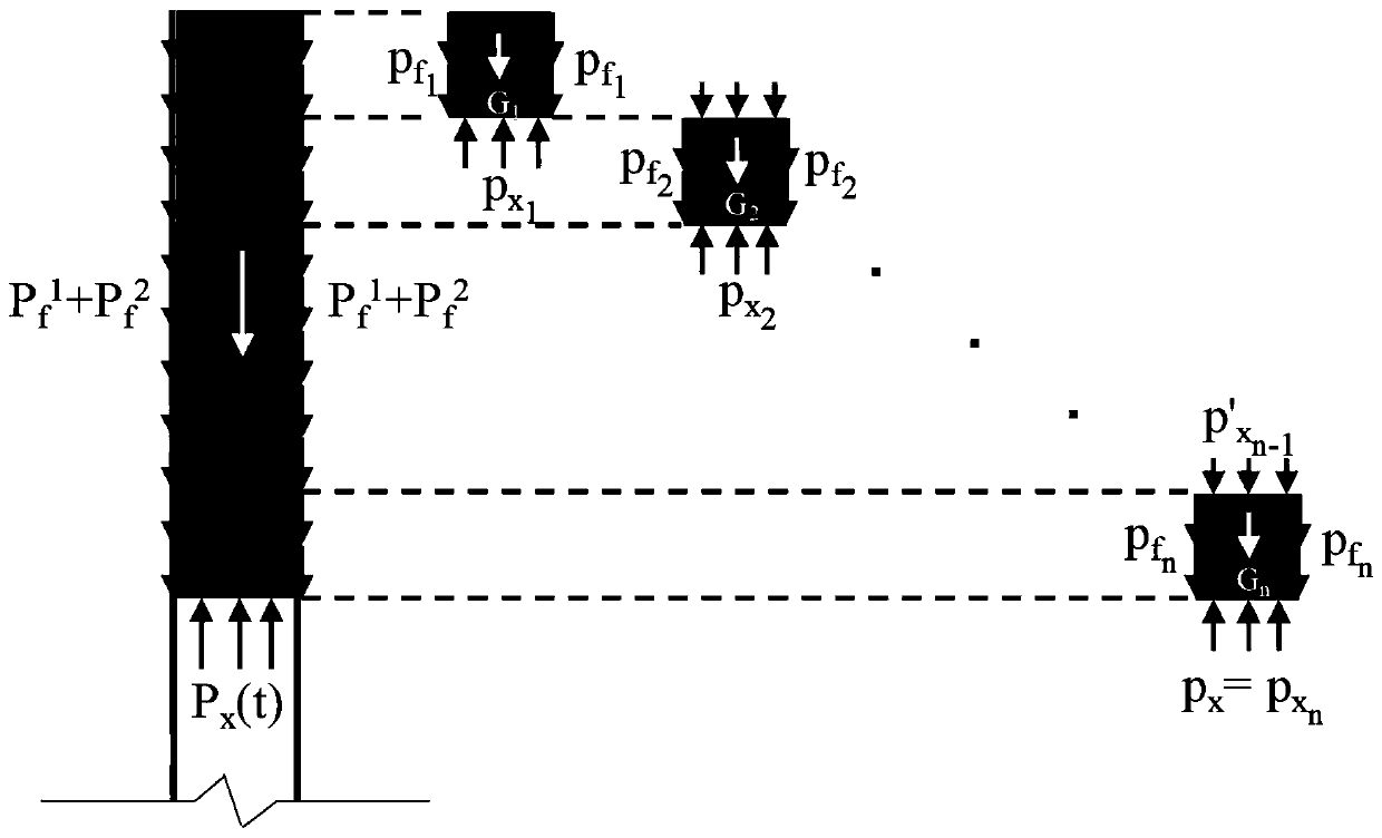
In terms of theoretical analysis, it is considered that the sliding friction force between the blasthole wall and the plugging structure is uniformly distributed along the axial direction, but it is not true. During the macroscopic movement, the sliding friction force on the bottom of the blasthole plugging structure is obviously greater than that of the plugging structure at the hole. The sliding friction force received is much greater, and the additional friction force generated by the compression and rebound of the blasthole blockage structure is not considered; in terms of design principles: there are two extremes, one is to blindly increase the frictional resistance between the blasthole blockage structure and the hole wall , the blasthole plugging structure basically does not move during the blasting process, making it difficult for the blasting gas to act on the rock mass around the plugging section, resulting in a serious large block rate at the hole opening. The second is that during the blasting process, the blasthole plugging The time for the structure to rush out of the blasthole is equal to the time for breaking the rock mass. In this way, the explosive gas is easy to release the pressure instantly from the orifice, and the range of action of the explosive gas is extended to the top of the orifice. In actual blasting, there is a broken area at the orifice itself. The blasting gas has little effect on the rock mass at the orifice, and it is easy to produce blasting flying rocks, which poses a certain safety hazard

Method used

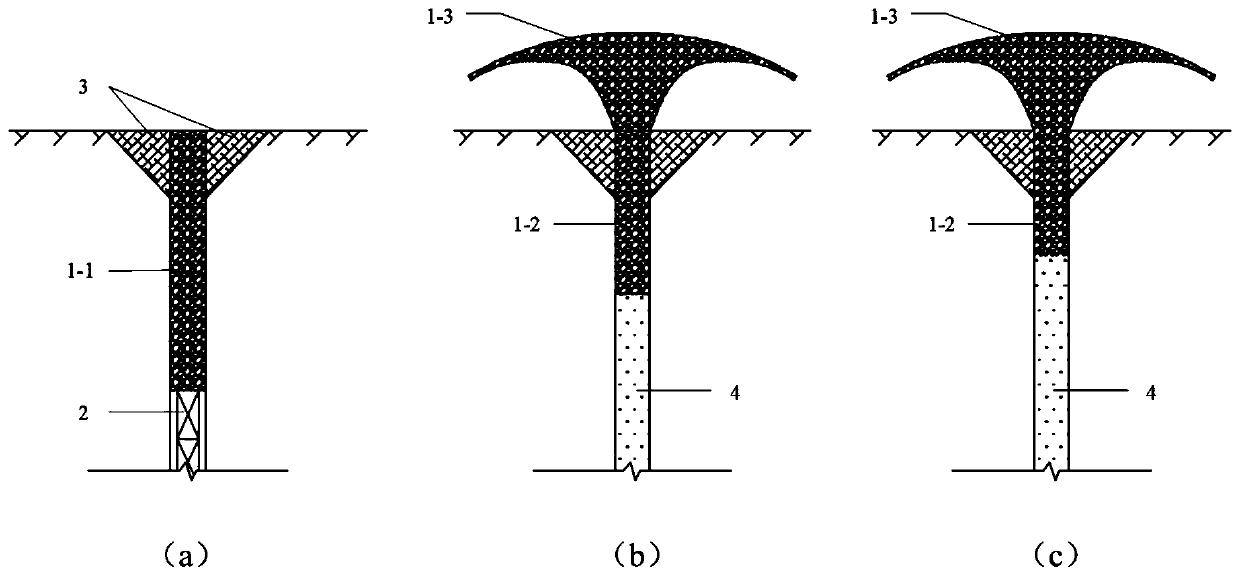
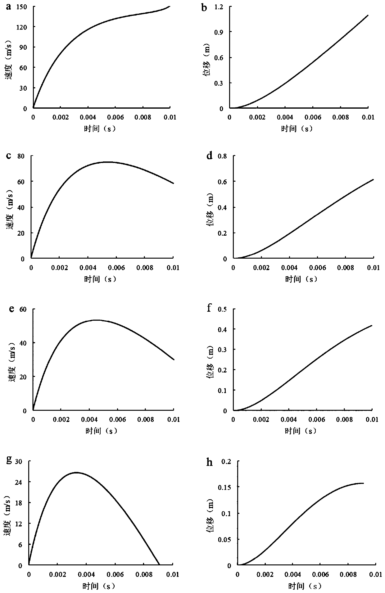

Image

  • Transport type blast hole blocking structure design method
  • Transport type blast hole blocking structure design method
  • Transport type blast hole blocking structure design method

Examples


Embodiment

[0055] In an open-pit quarry, deep-hole bench blasting is used for stone mining. The explosive is No. 2 rock emulsion explosive. The diameter of the drug coil is 70mm, the distance between the blast holes is 3.7m, and the row distance is 2.5m. Drilling cuttings are used to plug the hole, and the plugging length is determined to be 1.6m to 3.0m according to the blasting parameters such as the hole diameter and the chassis resistance line according to the empirical formula in the "Blasting Manual". When the length of the blast is set to a large value, some blastholes are punched, the blasting gas escapes from the hole prematurely, and the blasting flying rocks are relatively serious; It cannot act on the rock mass around the blockage section, and there are many large rock masses at the orifice, with a high rate of large blocks. It is difficult to reasonably select the blocking length, so the design method proposed by the present invention is used to determine the blocking lengt...


PUM


Abstract

The invention discloses a transport type blast hole blocking structure design method. The method comprises following steps of S1, based on blast design, determining a blast parameter; S2, carrying outstress analysis on a blast hole blocking structure, and calculating detonation gas expansion pressure, sliding friction force between a blast hole wall and the blocking structure, and blocking structure gravity; S3, determining a solving method of a blast hole blocking structure motion rule; S4, on the basis of a transport type design principle of the blast hole blocking structure, determining arange of a bottom motion distance of the blast hole blocking structure in the blast process; and S5, using a trial method to determine a range of an optical blocking length of the blast hole blockingstructure. The blast hole blocking structure optimized through the provided transport type design method is used, during blast, before the detonation gas pressure is relieved, the blast hole blockingstructure is allowed to move by a certain distance, but the structure does not rush out of a blast hole, thus the action range of detonation gas can be widened, a hole opening boulder yield is reduced, too early leakage of the detonation gas can be avoided, and the explosive energy use rate can be obviously improved.

Description

technical field [0001] The invention belongs to the technical field of engineering blasting, can be used in the design of rock mass blasting in the fields of mines, water conservancy and hydropower, transportation and the like, and relates to a method for designing a moving blast hole blocking structure. Background technique [0002] Blast hole plugging is an important link in blasting construction. Whether the hole is blocked or not has no obvious effect on the peak value of the blast shock wave, but the subsequent pressure reduction, especially the reduction of the explosion gas pressure and the time it takes to break the rock, are related to whether it is blocked or not. Due to the certain mass of the blasthole blockage, the gas produced after the explosion of the explosive will accelerate to a very high speed in an instant. If the gas wants to rush out of the blasthole hole, it must overcome the inertial resistance of the blockage and the gap between the blockage and the...

Claims


Application Information

Patent Timeline
Patent Type & Authority Applications(China)
IPC IPC(8): F42D1/18
CPCF42D1/18
Inventor 陈明叶志伟卢文波严鹏王高辉
Owner WUHAN UNIV
Why Eureka
Try Eureka