Centrifugal turbomachines having extended performance ranges

a technology of centrifugal turbomachines and performance ranges, which is applied in the direction of machines/engines, liquid fuel engines, separation processes, etc., can solve the problems of improving the usable operating range, achieving the apparent limit of usable range, and yielding minimal benefits

Active Publication Date: 2017-02-14
CONCEPTS ETI
View PDF58 Cites 14 Cited by
  • Summary
  • Abstract
  • Description
  • Claims
  • Application Information

AI Technical Summary

Benefits of technology

[0007]In one implementation, the present disclosure is directed to an apparatus. The apparatus includes a centrifugal turbomachine that includes: an impeller rotatable about a rotational axis and having: an inlet region located proximate to the rotational axis; an outlet region located distal from the rotational axis; and a plurality of blades extending between the inlet and outlet regions; an intake designed and configured to direct a working fluid to the inlet region of the impeller; and a performance-range-enhancing treatment applied to the intake and designed and configured to enhance the performance range of the centrifugal turbomachine; wherein the performance-range-enhancing treatment is a non-self-bleed treatment.
[0008]In another implementation, the present disclosure is directed to a method of extending the performance-range of a centrifugal turbomachine that includes: an impeller rotatable about a rotational axis and having: an inlet region located proximate to the rotational axis; an outlet region located distal from the rotational axis; and a plurality of blades extending between the inlet and outlet regions; and a casing circumferentially enshrouding the impeller so as to defined a blade-tip-clearance gap between the casing and the plurality of blades. The method includes injecting a high-momentum flow so as to reenergize flow within the blade-tip-clearance gap, wherein the high-momentum flow is not a flow from a self-bleed-type casing treatment of the centrifugal turbomachine.
[0009]In still another implementation, the present disclosure is directed to a method of extending the performance-range of a centrifugal turbomachine that includes an impeller rotatable about a rotational axis and having an inlet region located proximate to the rotational axis, and an outlet region located distal from the rotational axis. The method includes: during times of relatively low mass flow of a working fluid into the centrifugal turbomachine, directing substantially all of the working fluid to the inlet region of the centrifugal turbomachine through a primary flow region; and during times of relatively high mass flow of the working fluid into the centrifugal turbomachine, directing a portion of the working fluid to a secondary flow region radially outward from the primary flow region.

Problems solved by technology

In general terms regarding compressor performance requirements, the approach for reduced emissions via higher EGR utilization is in direct opposition to achieving a rated engine power condition.
As the operating range requirements are increased for a single stage centrifugal compressor, an apparent limit in usable range is reached.
Stable operating range can be increased further without improving the usable operating range, thus yielding minimal benefits.
To achieve the desired range in a single compressor requires compromises in the design process.

Method used


Image

  • Centrifugal turbomachines having extended performance ranges
  • Centrifugal turbomachines having extended performance ranges
  • Centrifugal turbomachines having extended performance ranges

Examples


Embodiment Construction

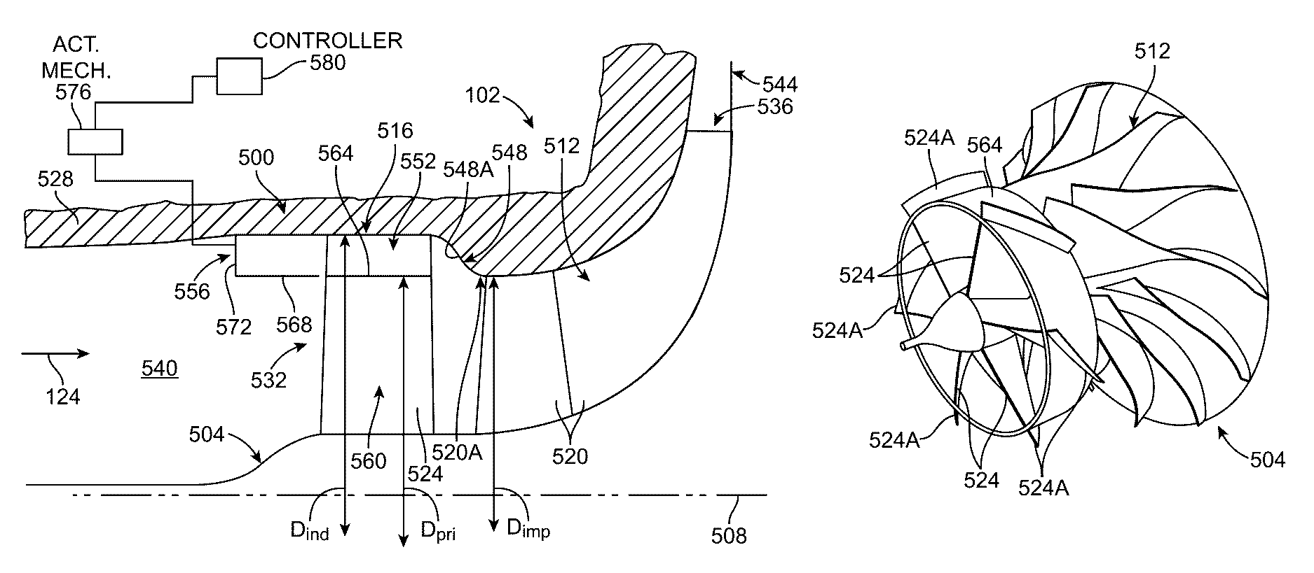
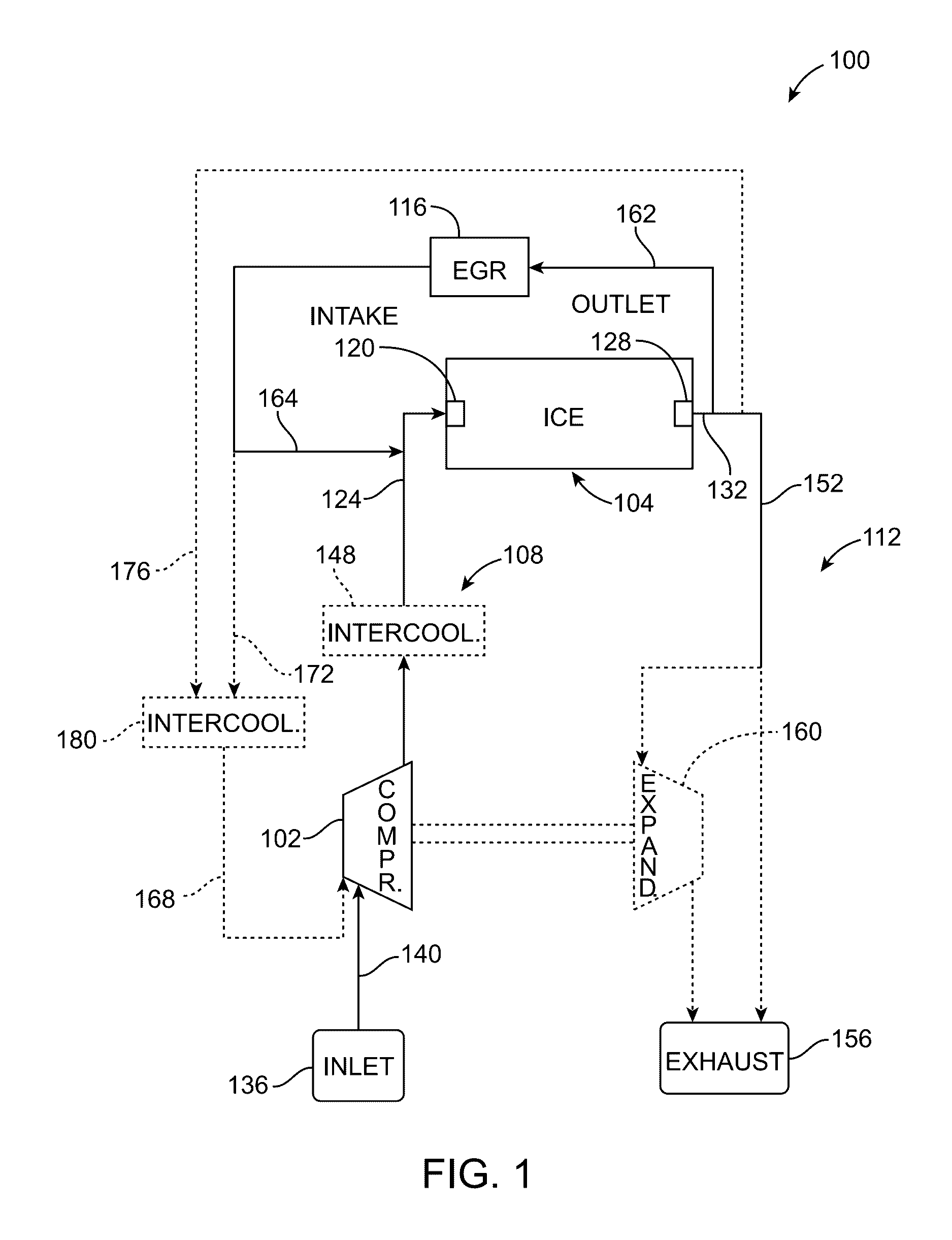
[0023]Referring now to the drawings, for illustrative purposes FIG. 1 shows an internal-combustion-engine (ICE) system 100 that includes a centrifugal turbomachine, here a centrifugal compressor 102, and an internal combustion engine (ICE 104). As will be described below in detail, centrifugal compressor 102 includes a unique treatment that functions to extend the performance range of the compressor and, in some cases, can also beneficially affect the performance envelope of ICE 104. However, before describing several examples of the unique compressor treatment, exemplary system 100 is described more fully to provide the reader with good context for those examples.

[0024]As seen in FIG. 1, ICE system 100 also includes a combustion-gas-charging system 108, an exhaust system 112, and an exhaust-gas-recirculation (EGR) system 116. As those skilled in the art will readily appreciate, ICE 104 includes an intake 120 for receiving a combustion-gas flow 124 from combustion-gas-charging syste...


PUM

PropertyMeasurementUnit
high-momentumaaaaaaaaaa
circumferenceaaaaaaaaaa
momentumaaaaaaaaaa

Abstract

Centrifugal turbomachines, such a centrifugal compressors, centrifugal blower, and centrifugal pumps, having unique treatments that enhance their performance ranges. In one arrangement, the treatment involves injecting a relatively high-momentum flow proximate to the blade-tip clearance gap at the inlet to the impeller of the turbomachine in a manner that reenergizes flow at the gap. The injected high-momentum flow can be taken from a location downstream of the outlet of the impeller and / or from a flow external to the turbomachine. In another arrangement, the non-self-bleed-type treatment involves providing the centrifugal turbomachine with a secondary flow path upstream of the inlet to the impeller. In one example, the flow of working fluid to the secondary flow path is modulated according to the mass flow of the working fluid. During times of higher flow, the secondary flow path is opened, and at times of lower flow, the secondary flow path is closed.

Description

RELATED APPLICATION DATA[0001]This application claims the benefit of priority of U.S. Provisional Patent Application Ser. No. 61 / 419,019, filed on Dec. 2, 2010, and titled “Systems and Methods for Extending the Performance Range of Centrifugal Compressors Using High-Momentum Flow Injection,” and U.S. Provisional Patent Application Ser. No. 61 / 419,021, filed on Dec. 2, 2010, and titled “Systems and Methods for Extending the Performance Range of Centrifugal Compressors Using a Modulated Inlet Flow Path,” each of which is incorporated by reference herein in its entirety.FIELD OF THE INVENTION[0002]The present invention generally relates to the field of centrifugal turbomachines. In particular, the present invention is directed to centrifugal turbomachines having extended performance ranges.BACKGROUND[0003]The performance characteristics of a given turbocharged internal combustion engine (ICE) rely on the proper selection and integration of turbomachinery elements. Component efficiency ...

Claims


Application Information

Patent Timeline
Patent Type & Authority Patents(United States)
IPC IPC(8): F02B33/44F02K1/36B01D46/00
CPCF02K1/36B01D46/0069F04D29/684F04D27/0238F04D29/4213B01D46/715
Inventor KRIVITZKY, ERIC M.LAROSILIERE, LOUIS M.
Owner CONCEPTS ETI
Why Eureka
Try Eureka