An Optimal Method for Arrangement of Irregular Subarrays Achieving High Gain

An optimization method and irregular technology, applied in the field of antennas, can solve problems such as gain drop, poor applicability, and increased gain loss, and achieve low sidelobe effects

Active Publication Date: 2020-10-13
UNIV OF ELECTRONICS SCI & TECH OF CHINA
View PDF10 Cites 2 Cited by
  • Summary
  • Abstract
  • Description
  • Claims
  • Application Information

AI Technical Summary

Problems solved by technology

[0003] R.J.Mailloux, Andrea Massa and others proposed the method of using irregular sub-arrays to break the periodicity of the array, but because the optimization problem is too complicated, their scheme can only realize one-dimensional scanning, which is poor in engineering applicability
The patent No. CN 107230843 A adopts a similar scheme to realize two-dimensional scanning, but the scanning performance is not strong. The sub-arrays composed of two units are arranged at 0.7 wavelength intervals under the 20×20 array. Only two-dimensional scanning of ±20° can be realized. This solution has not fully utilized the scanning advantages of irregular sub-arrays, and its applicability in engineering is poor.
The patent No. CN108808266A also adopts the optimization scheme based on the principle of maximum entropy, but when it is applied to the quadruple grid (that is, the sub-array composed of four units), the scanning capabilities of each surface of the two-dimensional scanning will be inconsistent. Simultaneous scanning smaller angle
The most important thing is that none of the above documents specifically optimize the gain level during scanning. Although the irregular subarray can achieve high-gain radiation during side-firing, as the scanning angle continues to increase, due to the influence of the wave path difference, the gain The decline is more drastic, especially for the quadruple grid with a higher sparse rate, the array gain of the scheme with the patent number CN108808266A is 4.6dB lower than that of the Taylor array of the same scale when scanning to 30 degrees. As the scan angle gradually increases, the gain loss will further increase

Method used


Image

  • An Optimal Method for Arrangement of Irregular Subarrays Achieving High Gain
  • An Optimal Method for Arrangement of Irregular Subarrays Achieving High Gain
  • An Optimal Method for Arrangement of Irregular Subarrays Achieving High Gain

Examples


Embodiment Construction

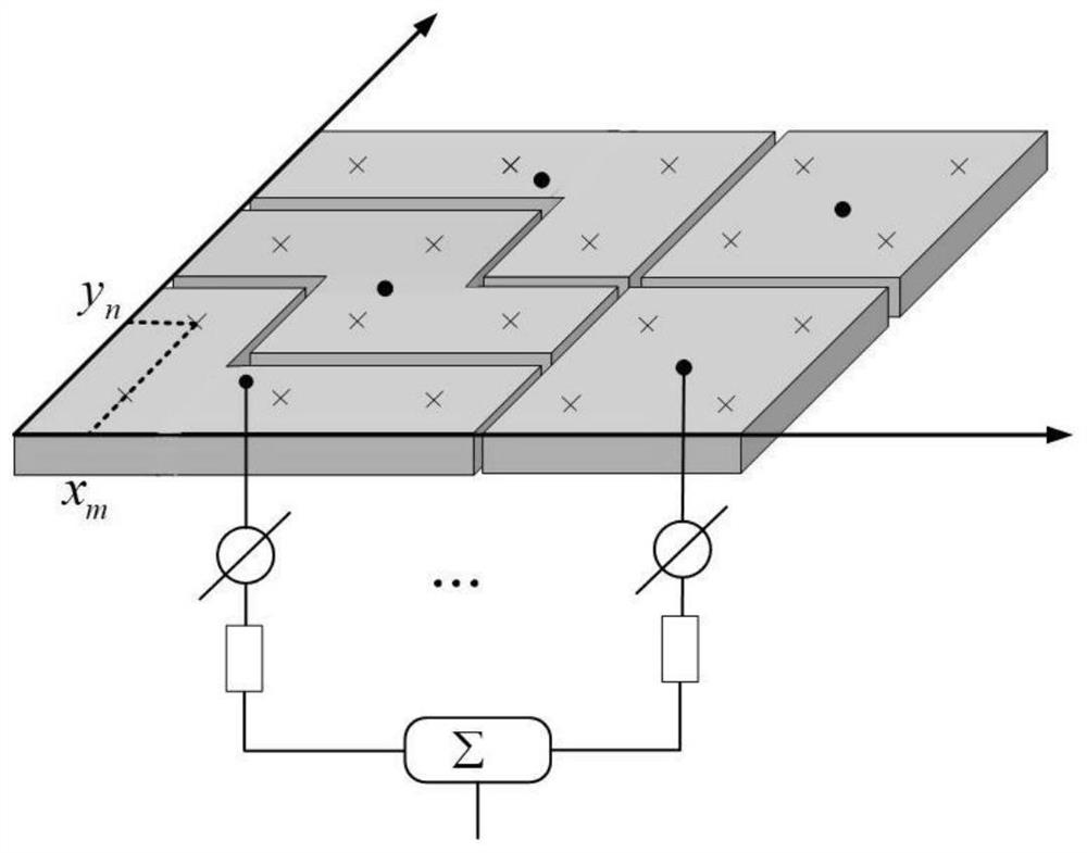
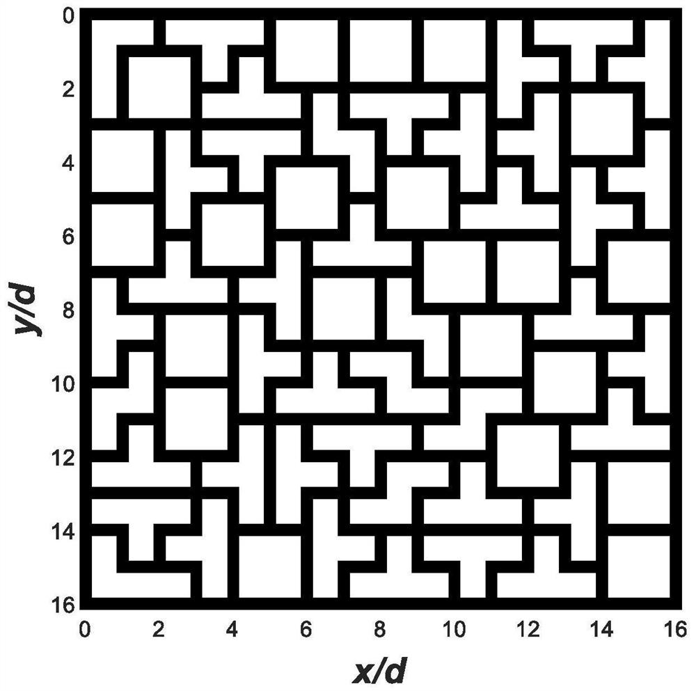
[0033] Consider an irregular array, the size of the array is M×N=16×16, considering that the irregular sub-array is composed of 4 array units, so there are 16×16 / 4=64 sub-arrays in total, and the antenna units in the sub-array The excitation amplitude and excitation phase are the same, and the difference between the array information entropy and the limit value of information entropy is set to σ=0.05. The reference array is a Chebyshev planar array with 16×16=256 units.

[0034] Other main parameters are as follows:

[0035] d=d x = d y =0.5λ

[0036] The first step is to optimize the arrangement of irregular sub-arrays through a commercial solver, such as image 3 , to obtain an irregular array with a total of 64 sub-arrays, the optimized information entropy of the array is H=6.6639, and the limit value of information entropy is log 2 (MN / 2)=7. In the second step, the amplitude and phase distribution under the desired pattern are obtained by optimizing the convex optimiza...


PUM


Abstract

The invention discloses a phased array arrangement optimization method based on irregular sub-arrays, and proposes a mixed integer linear programming model, while considering the gain and sidelobe level during array scanning, and solving it by a commercial solver to realize The high gain and low sidelobe characteristics of irregular array scanning, after optimizing the array arrangement, use the convex optimization algorithm to synthesize the required pattern based on the principle of maximum gain.

Description

technical field [0001] The invention belongs to the technical field of antennas, relates to an optimization method for irregular sub-array arrangement, proposes a mixed integer programming model, considers the gain and side lobe level during array scanning, and finally realizes high gain and high efficiency during irregular array scanning. Low sidelobe characteristics. Background technique [0002] Phased array antennas are widely used in the radar and communication fields because they can achieve the purpose of beam scanning by changing the phase. At the same time, the amplitude and phase weighting methods of conventional phased arrays are difficult to meet the requirements of low sidelobes of antenna arrays, which limits the application range of antennas. Sparse array antenna, through the sparse arrangement of antenna elements, reduces grating lobes to realize pattern scanning, but the sparse array has many problems such as processing and inter-unit coupling, so it is not...

Claims


Application Information

Patent Timeline
Patent Type & Authority Patents(China)
IPC IPC(8): G06F30/20G06F30/18H01Q3/26G06F111/04
CPCH01Q3/26
Inventor 杨仕文马彦锴陈益凯屈世伟胡俊
Owner UNIV OF ELECTRONICS SCI & TECH OF CHINA
Why Eureka
Try Eureka