
Battery cell system

A battery cell and management system technology, applied in circuits, current collectors, electric vehicles, etc., can solve the problems that users cannot monitor and prepare in advance, fire, high cost, etc., to improve reliability and ease of maintenance, and reduce complexity and cost, monitor and control fine-grained effects

Inactive Publication Date: 2020-05-29
ZHANGJIAGANG MOTOPU DATA TECH CO LTD
View PDF9 Cites 0 Cited by
  • Summary
  • Abstract
  • Description
  • Claims
  • Application Information

AI Technical Summary

Problems solved by technology

[0005] 2. At present, the charging and discharging protection chips of lithium batteries control the battery work in real time, and do not have the ability to record detailed information about the working status of the battery
Even if the data is collected and recorded through the battery management system, the data is stored on the computer of the application system, that is, stored on the terminal computer, and the important historical information of the battery cannot be tightly bound to the battery itself
For battery cascade utilization, one battery needs to serve multiple application systems. When migrating a lithium battery from one user system to another, it is difficult to obtain and utilize historical data of the battery
[0006] 3. The battery management system only monitors and protects the charging and discharging of lithium batteries in the working system, and other links such as storage and transportation are monitoring blind spots
For example, the monitoring of the battery's own temperature or the surrounding temperature cannot be controlled in real time. Once the temperature of the battery rises due to its own problems or the bad surrounding environment, causing a fire, the user cannot monitor and prevent in advance.
[0007] 4. In the existing battery monitoring scheme, the transmission of information needs to use a special data line. If each battery cell is to be used as an independent object for information collection and control, each battery cell needs to be connected to an additional data line. This will add a large number of data lines in the battery pack, resulting in high cost, complex structure, high failure rate, and difficult maintenance

Method used


Image

  • Battery cell system
  • Battery cell system
  • Battery cell system

Examples


Embodiment Construction

[0039] The present invention will be described in detail below in conjunction with specific embodiments shown in the accompanying drawings.

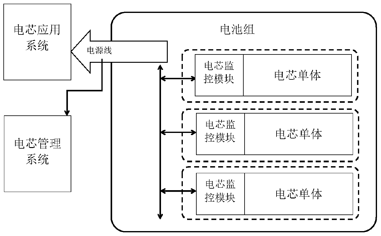
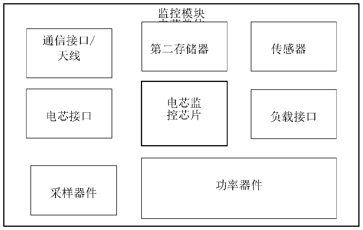
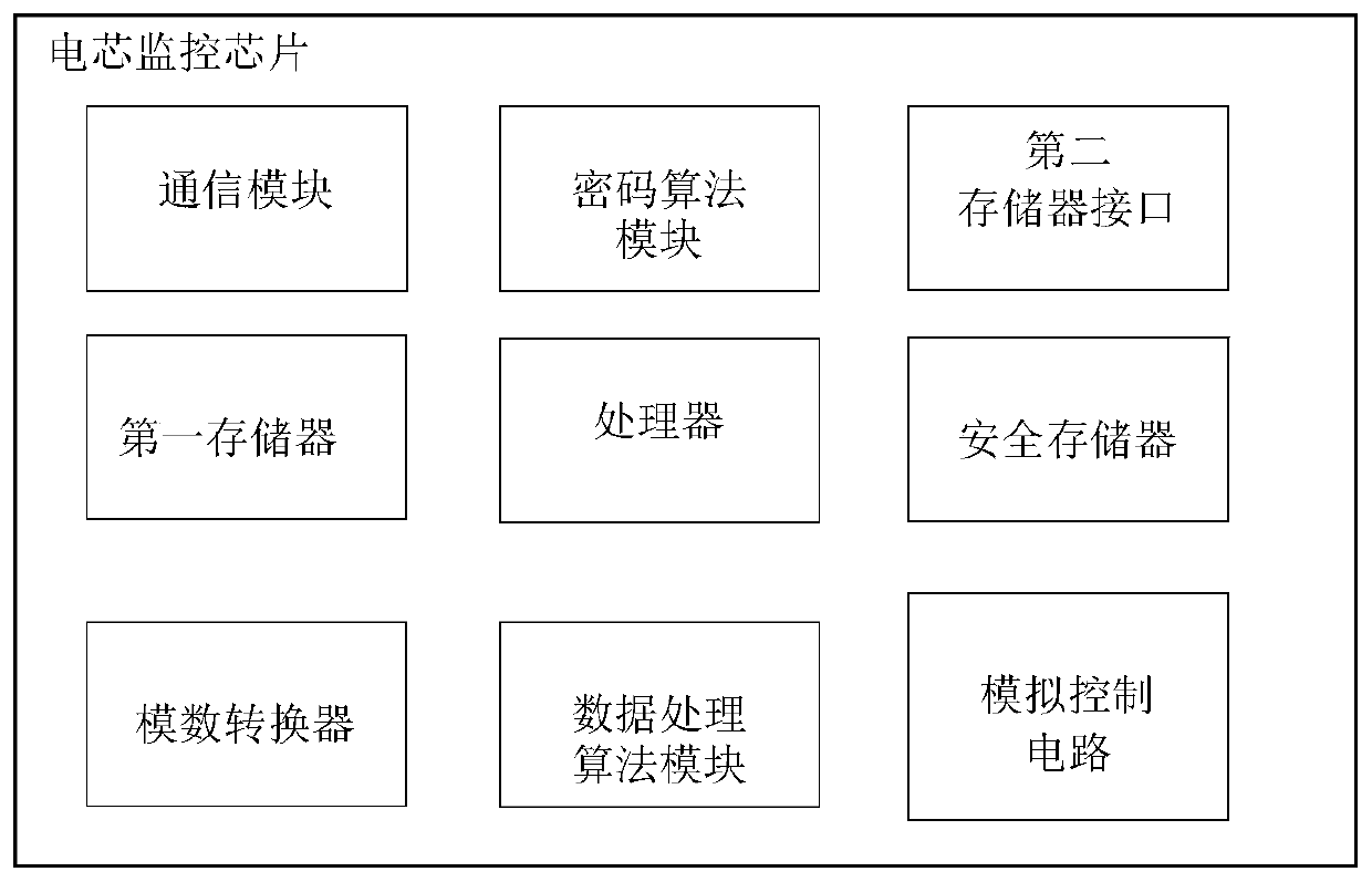
[0040] This embodiment provides a cell system, such as figure 1 , 2 , including a cell management system, a battery pack, a cell application system, and a power line connecting the battery pack and the cell application system, the battery pack includes at least one cell, and the cell includes a package that is combined and electrically powered The cell monomer and the cell monitoring module are connected in a positive manner, and the cell monitoring module is provided with a communication module, and the communication module realizes the reception of data information through the power line carrier communication or radio frequency wireless communication and the cell management system and pass. The cell monitoring module includes a cell monitoring chip, a sensor, a sampling device, and the sensor is used to collect the working state of t...


PUM


Abstract

The invention relates to a battery cell system. The system comprises a battery cell management system and a battery pack; the battery pack comprises at least one battery cell; the battery cell comprises a battery cell unit and a battery cell monitoring module which are packaged and combined together and are electrically connected with each other; a communication module is arranged in the battery cell monitoring module; the communication module receives and transmits data information from and to the battery cell management system through a power line carrier communication or radio frequency wireless communication mode. According to the system of the invention, the state of each battery cell can be monitored in real time, and the communication between each battery cell monitoring module andthe battery cell management system can be realized without the additional arrangement of a data line.

Description

technical field [0001] The invention relates to a battery system, in particular to a battery system using a brand-new communication method. Background technique [0002] Lithium batteries are currently the most widely used electrochemical energy storage components. Due to their special structure and characteristics, battery monitoring and management circuits are an essential part of lithium battery application systems. In the current application of lithium batteries, for small single-cell batteries, each battery is generally equipped with a battery protection board; a battery pack with multiple cells connected in series and parallel is equipped with a battery management system. The core of the battery protection circuit and battery management system is the lithium battery protection and management chip. A simple lithium battery protection chip can realize overvoltage, overcurrent and overtemperature protection; the management system of the lithium battery pack is composed o...

Claims


Application Information

Patent Timeline
Patent Type & Authority Applications(China)
IPC IPC(8): H01M10/42H01M10/052H02J7/00
CPCH01M10/052H01M10/425H01M2010/4271H01M2010/4278H02J7/0029Y02E60/10
Inventor 桑胜田
Owner ZHANGJIAGANG MOTOPU DATA TECH CO LTD
Learn More