Eureka AIR delivers breakthrough ideas for toughest innovation challenges, trusted by R&D personnel around the world.

Rough machining device for metal tray production

A metal pallet and rough machining technology, which is applied in the direction of metal processing equipment, metal processing machinery parts, manufacturing tools, etc., can solve the problems of personnel injury, noise pollution environment, sparks or waste chips splashing, etc., and achieve the effect of convenient collection of waste chips

Inactive Publication Date: 2020-06-02
江苏华正数控机械有限公司
View PDF0 Cites 2 Cited by
  • Summary
  • Abstract
  • Description
  • Claims
  • Application Information

AI Technical Summary

Problems solved by technology

[0005] Aiming at the deficiencies of the prior art, the present invention provides a rough machining device for the production of metal trays, which has the advantages of convenient collection of waste chips, etc., and solves the problem that waste chips are attached to the hole wall, which is inconvenient to collect and process, and will cause problems during drilling work. It produces a lot of noise and pollutes the environment, and also produces sparks or waste debris splashing, causing damage to personnel and posing safety hazards

Method used


Image

  • Rough machining device for metal tray production
  • Rough machining device for metal tray production
  • Rough machining device for metal tray production

Examples


Embodiment Construction

[0027] The following will clearly and completely describe the technical solutions in the embodiments of the present invention with reference to the accompanying drawings in the embodiments of the present invention. Obviously, the described embodiments are only some, not all, embodiments of the present invention. Based on the embodiments of the present invention, all other embodiments obtained by persons of ordinary skill in the art without making creative efforts belong to the protection scope of the present invention.

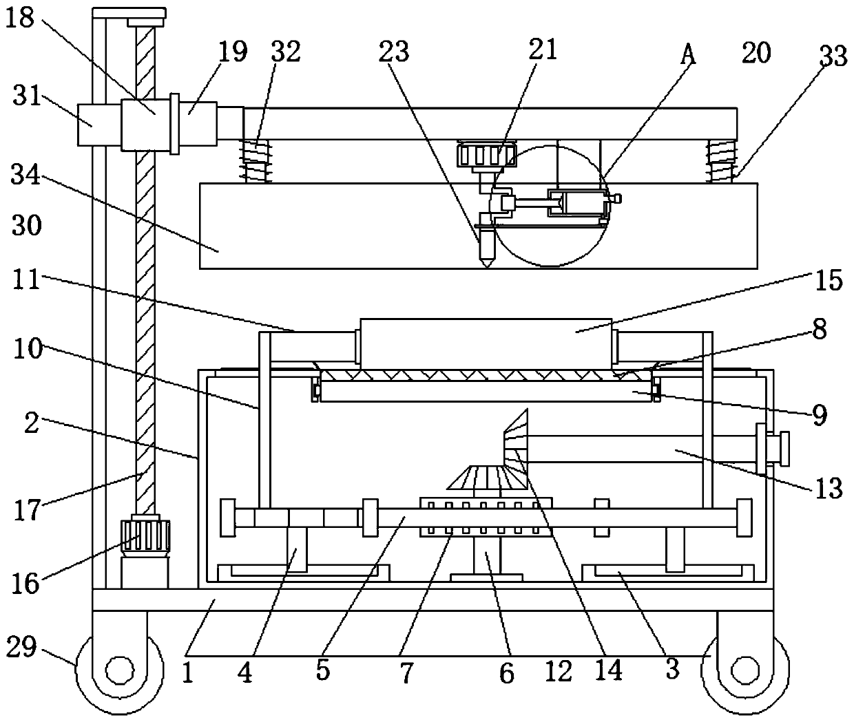
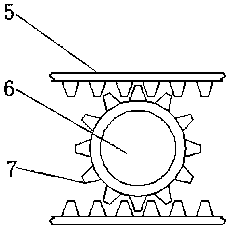
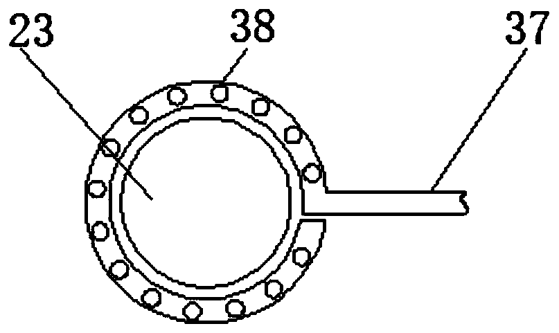
[0028] see Figure 1-4 , a rough machining device for metal pallet production, comprising a base plate 1, four wheels 29 are arranged on the lower surface of the base plate 1, and the four wheels 29 are evenly distributed on the lower surface of the base plate 1, so as to facilitate movement and use, The upper surface of the bottom plate 1 is fixedly connected with an inner hollow workbench 2, and the inner bottom wall of the workbench 2 is fixedly connected w...


PUM


Abstract

The invention relates to the technical field of metal trays, and discloses a rough machining device for metal tray production. The rough machining device comprises a bottom plate. The upper surface ofthe bottom plate is fixedly connected with an internally hollow workbench. Two sliding rails are fixedly connected to the inner bottom wall of the workbench. The interiors of the two sliding rails are slidably connected with sliding blocks. The top ends of the two sliding blocks are fixedly connected with two racks. The upper surface of the bottom plate is rotationally connected with a circular column through a bearing. The two sliding blocks are symmetrically distributed with respect to the circular column. According to the rough machining device for metal tray production, when a material isdrilled, a working motor drives a crankshaft to rotate, a sleeve drives a connecting rod to move, the connecting rod pulls a piston to move, gas in the piston is exhausted through a gas outlet nozzle, a gas pipe and an annular gas spray nozzle, the outer surface of a drilling cutter is sleeved with the annular gas spray nozzle, waste chips generated in the drilling process are blown into a wastebox, and the effect of conveniently collecting the waste chips is achieved.

Description

technical field [0001] The invention relates to the technical field of metal pallets, in particular to a rough processing device for the production of metal pallets. Background technique [0002] The metal pallet is designed according to the standard size series of the international standard ISO6780, which is standardized and universal, and is suitable for various intermodal transportation methods in different countries. Transportation, warehousing and transportation of electronics, food, medicine and chemical products. Pallets (also known as pallets) play an important role in modern storage and transportation, and their materials are generally divided into wood, plastic, paper, metal, plywood, etc. [0003] Metal trays need to go through rough machining processes such as drilling, stamping, cutting and polishing during production. When drilling, a large amount of waste will be generated, which will affect the smoothness of the inner wall of the hole, and the waste will adh...

Claims


Application Information

Patent Timeline
Patent Type & Authority Applications(China)
IPC IPC(8): B23B41/00B23B47/00B23Q11/00B23Q11/08
CPCB23B41/00B23B47/00B23Q11/005B23Q11/08
Inventor 葛昆鹏
Owner 江苏华正数控机械有限公司
Why Eureka
Eureka Blog
Learn More