
Method and Application of Longitudinal Machining Using Inverse Spherical Aberration Correction

A spherical aberration, vertical technology, applied in the field of micro-optical element processing, can solve the problems of unfavorable device miniaturization, long processing time, grating interlacing, etc., to improve processing efficiency and structural quality, improve processing resolution, and increase processing depth. Effect

Active Publication Date: 2021-03-30
JILIN UNIV
View PDF13 Cites 0 Cited by
  • Summary
  • Abstract
  • Description
  • Claims
  • Application Information

AI Technical Summary

Problems solved by technology

However, the former takes a long time to process, and the superimposed grating is prone to interlacing, which reduces the quality of the optical diffraction element
The latter, due to the reduced numerical aperture, leads to low processing resolution, which is not conducive to the miniaturization of devices

Method used


Image

  • Method and Application of Longitudinal Machining Using Inverse Spherical Aberration Correction
  • Method and Application of Longitudinal Machining Using Inverse Spherical Aberration Correction
  • Method and Application of Longitudinal Machining Using Inverse Spherical Aberration Correction

Examples


Embodiment 1

[0030] Dellar is obtained by using anti-ball line differential correction.

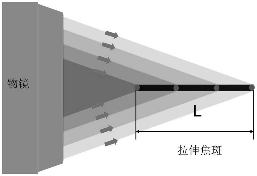
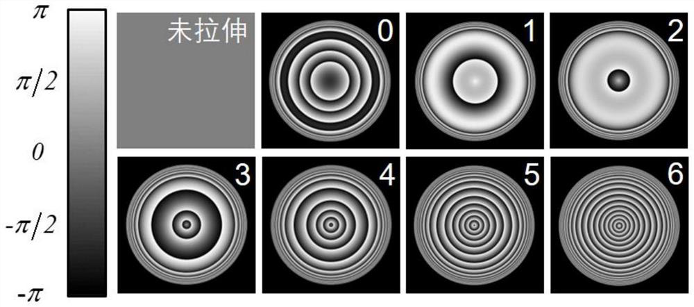
[0031] According to the Booth formula, the focus is modulated to focus on the femtosecond laser focus in the material to be processed, that is, the phase compensation factor S is expanded from the original single value to a section [S-F st / 2, s + f st / 2] So that the focus spots are significantly stretched along the longitudinal direction, thereby obtaining a linear focal spot that can be processed in a longitudinal direction than longitudinal direction.

[0032] Using the anti-ball difference correction to obtain stretching inside to be processed, the specific steps are as follows:

[0033] (1), expand the compensation factor S to obtain anti-ball difference correction phase compensation hologram: First, introduce stretch factor forth for Booth formulas st , Enabling the compensation factor S with value in [S-F st / 2, s + f st The interval of / 2], that is, the value is to expand from the original si...

Embodiment 2

[0040] The nano-raster structure of the large depression ratio is used with stretching.

[0041] When the repetition frequency of the femtosecond laser is high, a continuous line or face can be obtained by point-by-point scan. Using the flyosecond laser stretch spot laser inside the material to be processed, a parent-by-point scan is performed in the Z-axis direction (setting the cross section of the drawpuce) to obtain a nano-raster structure along the XY plane. (Ie a series of equivalents of a series of equivalents perpendicular to the XY plane).

[0042] The specific steps are as follows: The specific steps are as follows:

[0043] (1), expand the compensation factor S to obtain a transmissive chart of anti-ball difference correction phase compensation: the same embodiment, where F st The value is 20, and the extended range of S-10, S + 10 is obtained.

[0044] (2), the modulation phase obtains the stretch spot: in Example 1, wherein the focus depth of the objective lens is 500...


PUM


Abstract

The invention discloses a method for longitudinal processing using anti-spherical-aberration correction and application, and belongs to the technical field of femtosecond laser processing. The methodfor longitudinal processing using anti-spherical-aberration correction comprises the steps that anti-spherical-aberration correction is carried out on a femtosecond laser focus through a spatial lightmodulator, and a focal spot significantly stretching in the longitudinal direction is obtained from the deeper part of inside of a material to be processed, so that the stretched focal spot is directly used for continuously scanning inside of the material to be processed to achieve longitudinal processing with a large ratio of pit-depth to pit-diameter. Anti-spherical-aberration correction is used for obtaining the linear focal spot stretching significantly in the longitudinal direction, a longitudinal structure with a large ratio of pit-depth to pit-diameter can be processed inside the material at one time without requiring more than once processing to accumulate the longitudinal depth of the structure, structure staggering caused by more than once processing is avoided, the processing efficiency and structural quality are improved, the situation that the numerical aperture NA is reduced to increase the processing depth is not required, and the processing resolution is improved.

Description

Technical field [0001] The present invention belongs to the field of femtosecond laser processing, and more particularly to the longitudinal stretching of femtosecond laser focus to achieve high precision, longitudinally uniform micro-optical element processing using anti-ball difference correction. Background technique [0002] The micro-optical component is the basic component of micro-photomics, and it has important applications in optical chips, micro-optical treatment. Frequiper laser processing technology has become one of the main techniques of processing micro-optical devices due to its high processing accuracy, high patterning levels, and effective modification of materials. Taking quartz material as an example, femtosecond laser can induce nano-grating structure at higher power, and its high pulse energy can significantly change the refractive index of the inducible region (up to 10 -3 Summary), thereby obtaining an optical diffractive element. In order to improve the e...

Claims


Application Information

Patent Timeline
Patent Type & Authority Patents(China)
IPC IPC(8): B23K26/55B23K26/082B23K26/06
CPCB23K26/0613B23K26/082B23K26/55
Inventor 孙洪波樊华陈岐岱
Owner JILIN UNIV
Learn More