Supercharge Your Innovation With Domain-Expert AI Agents!

Connection rod assembly for piston compressor

A technology of connecting rod components and compressors, which is applied in the direction of variable capacity pump components, liquid variable capacity machines, pump components, etc., can solve problems such as easy breakage, large force on the small end of the connecting rod, and machine damage, etc., to achieve Reduce economic losses, reduce maintenance frequency, and improve practicability

Inactive Publication Date: 2020-06-02
段继东
View PDF0 Cites 0 Cited by
  • Summary
  • Abstract
  • Description
  • Claims
  • Application Information

AI Technical Summary

Problems solved by technology

[0002] In the piston machine, the connecting rod is an important part. The small end of the connecting rod is connected to the piston pin, and the large end of the connecting rod is connected to the crankshaft, which converts the rotational motion of the crankshaft into the reciprocating motion of the piston to complete the working cycle of the compressor. The connection between the small head of the rod and the rod body bears a large force and is prone to breakage, especially in semi-hermetic piston compressors for refrigeration. Due to the incomplete evaporation of fluorine in the process of suction and exhaust of the compressor, the The formation of liquid fluorine will cause the material in the cylinder to not be discharged in time when the compressor is exhausted. When the piston continues to move in the original way, the small end of the connecting rod and the shaft will break, and the machine will be damaged.

Method used


Image

  • Connection rod assembly for piston compressor
  • Connection rod assembly for piston compressor
  • Connection rod assembly for piston compressor

Examples


Embodiment Construction

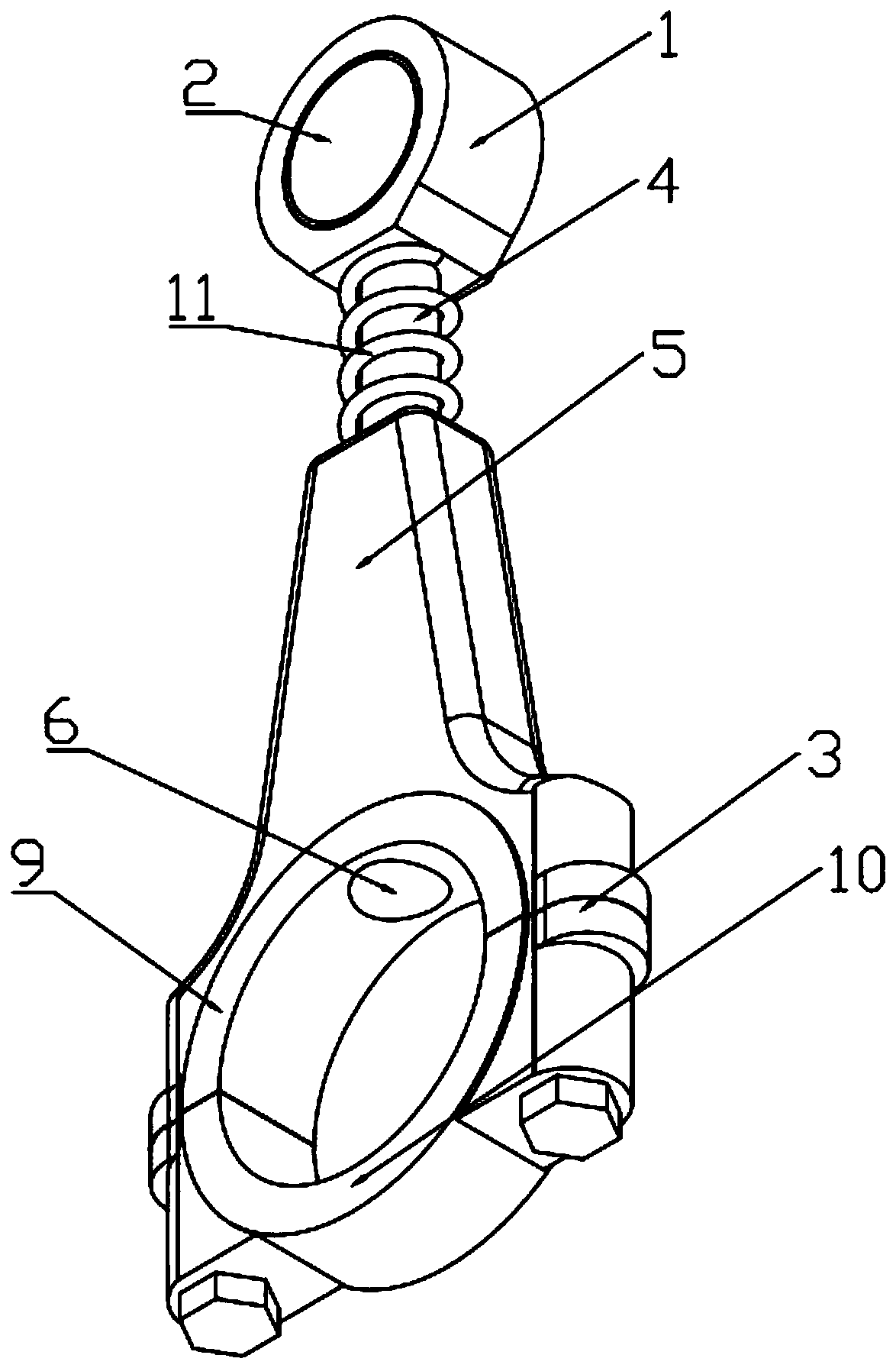
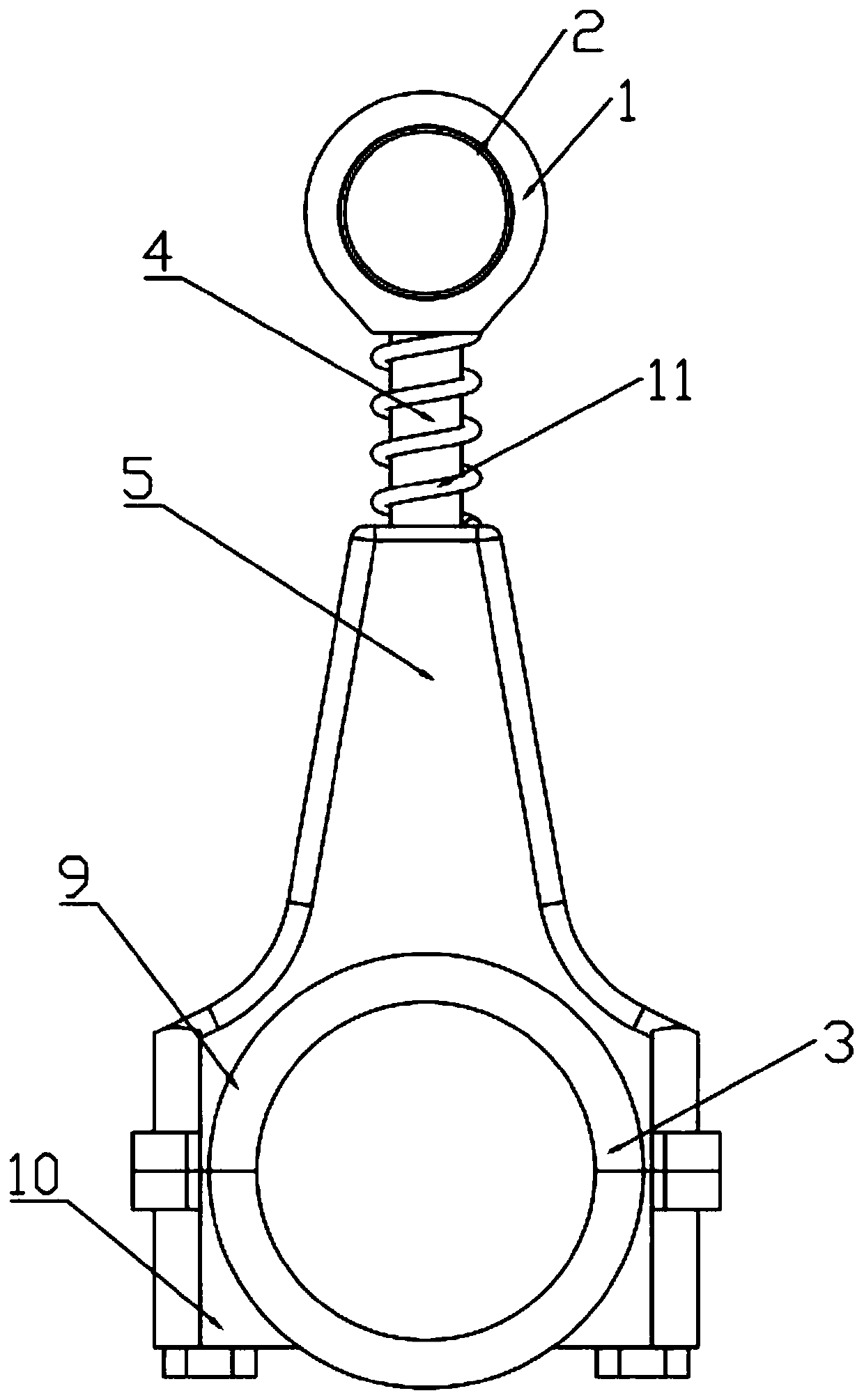
[0019] A connecting rod assembly for a piston compressor of the present invention will be further described in detail below in conjunction with the accompanying drawings.

[0020] combined with Figure 1-7 , a connecting rod assembly for a piston compressor, comprising a connecting rod small end 1, a small end bushing ring 2, and a connecting rod large end device 3; the connecting rod small end 1 is fixedly connected with a first connecting rod 4, and the connecting rod The rod big end device 3 is fixedly connected with a second connecting rod 5, and the second connecting rod 5 is provided with a sliding hole 6 along its extending direction, and the sliding hole 6 is provided with an inner hexagonal hole 7, and the first connecting rod 4 is provided with a hexagonal prism 12 that is slidingly fitted with the inner hexagonal hole 7 at the end away from the small end 1 of the connecting rod, and the end of the hexagonal prism 12 away from the small end 1 of the connecting rod is...


PUM


Abstract

The invention discloses a connecting rod assembly for a piston compressor. The connecting rod assembly comprises a connecting rod small end, a small end liner ring and a connecting rod large end device; a first connecting rod is fixedly connected to the connecting rod small end, a second connecting rod is fixedly connected to the connecting rod large end device, a sliding hole is formed in the extending direction of the second connecting rod, an inner hexagonal prism hole is formed in the sliding hole, a hexagonal prism is arranged at the end, away from the connecting rod small end, of the first connecting rod, a limiting sliding column is fixedly connected to the end, away from the connecting rod small end, of the hexagonal prism, and a spring is arranged between the connecting rod smallend and the second connecting rod. In a natural state, under the effect of elastic force of the spring, the first connecting rod extends out relative to the second connecting rod to the limiting sliding column to be in close fit with the table face of the inner hexagonal prism hole. The problem that pistons on the connecting rods cannot move to the normal stroke position due to liquid substances generated in a cylinder body when the compressor operates, so that the connecting rods are broken and damaged when the connecting rods continue to move is solved, the maintenance frequency of the compressor is greatly reduced, the economic loss is reduced, use is convenient, and practicability is good.

Description

technical field [0001] The invention relates to the technical field of piston compressors, in particular to a connecting rod assembly for a piston compressor. Background technique [0002] In the piston machine, the connecting rod is an important part. The small end of the connecting rod is connected to the piston pin, and the large end of the connecting rod is connected to the crankshaft, which converts the rotational motion of the crankshaft into the reciprocating motion of the piston to complete the working cycle of the compressor. The connection between the small head of the rod and the rod body bears a large force and is prone to breakage, especially in semi-hermetic piston compressors for refrigeration. Due to the incomplete evaporation of fluorine in the process of suction and exhaust of the compressor, the The formation of liquid fluorine will cause the material in the cylinder to not be discharged in time when the compressor is exhausted. When the piston continues t...

Claims


Application Information

Patent Timeline
Patent Type & Authority Applications(China)
IPC IPC(8): F04B39/00
CPCF04B39/00
Inventor 段继东
Owner 段继东
Features
  • R&D
  • Intellectual Property
  • Life Sciences
  • Materials
  • Tech Scout
  • Unparalleled Data Quality
  • Higher Quality Content
  • 60% Fewer Hallucinations
Learn More