
Check valve for fire fighting

A check valve and fire protection technology, applied in valve details, control valves, valve devices, etc., can solve the problems of large valve body, increased processing cost, and heavy valve weight.

Inactive Publication Date: 2020-06-02
SHANDONG YIBAITONG PIPELINE SYST CO LTD
View PDF1 Cites 1 Cited by
  • Summary
  • Abstract
  • Description
  • Claims
  • Application Information

AI Technical Summary

Problems solved by technology

Since the action direction of the spool is perpendicular to the flow direction of the liquid, the valve body needs to be designed with a special structure for the spool, resulting in a larger valve body, which makes the weight of the entire valve larger, and increases the processing cost. Difficulty and labor intensity of on-site construction
Especially when working at heights, the weight of the valve significantly increases the difficulty of the operation
[0004] In summary, there are obviously inconveniences and defects in the actual use of the existing technology, so it is necessary to improve

Method used


Image

  • Check valve for fire fighting
  • Check valve for fire fighting
  • Check valve for fire fighting

Examples


Embodiment Construction

[0029] In order to make the objectives, technical solutions and advantages of the present invention clearer, the present invention will be described in further detail below in conjunction with the accompanying drawings and embodiments. It should be understood that the specific embodiments described here are only used to explain the present invention and are not intended to limit the invention.

[0030] In describing the present invention, it should be understood that the terms "center", "longitudinal", "transverse", "length", "width", "thickness", "upper", "lower", "front", " Back", "Left", "Right", "Vertical", "Horizontal", "Top", "Bottom", "Inner", "Outer", "Clockwise", "Counterclockwise", "Axial", The orientation or positional relationship indicated by "radial", "circumferential", etc. is based on the orientation or positional relationship shown in the drawings, and is only for the convenience of describing the present invention and simplifying the description, rather than ...


PUM


Abstract

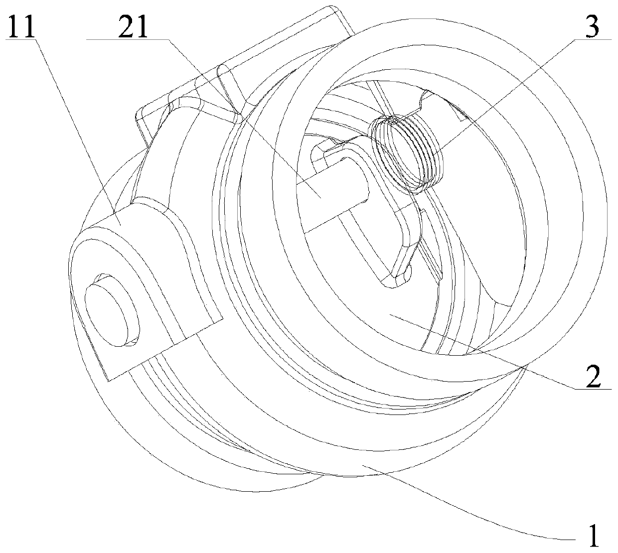
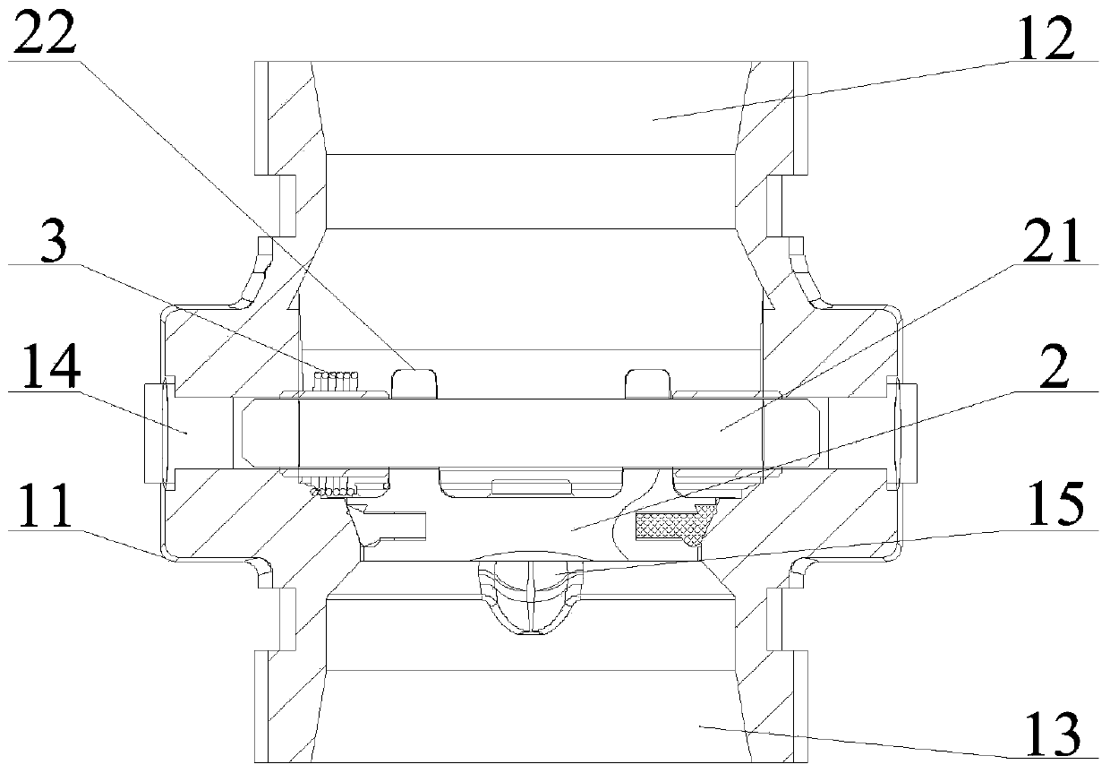
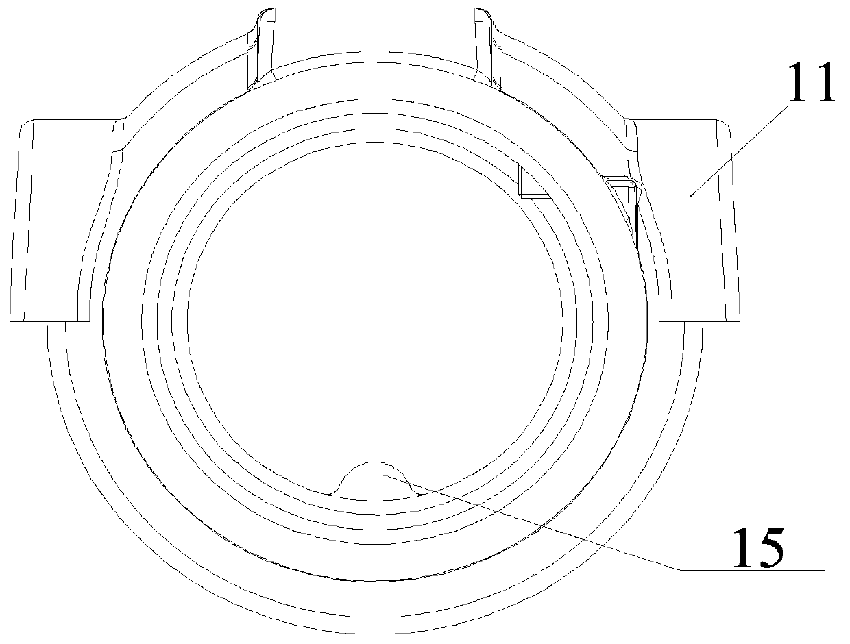
The invention relates to the technical field of valves, and provides a check valve for fire fighting. The check valve comprises a valve body, wherein the valve body is provided with a water outlet anda water inlet; a valve plate is disposed in an inner cavity of the valve body; the end face, facing the water outlet, of the valve plate is provided with shaft frame plates; a rotating shaft is movably connected with the shaft frame plates in a penetrating mode; two shaft seats are integrally arranged on the valve body, and a through hole is formed in each shaft seat; two ends of the rotating shaft movably sleeve the through holes; the rotating shaft and the circle center of the valve plate are provided with eccentric distances; a torsion spring for resetting the valve plate also sleeves therotating shaft; the diameter, facing the one side of the water outlet, of the valve plate is larger than the diameter, facing one side of the water inlet, of the valve plate; a sealing structure is arranged on the outer circumferential surface of the valve plate; and the sealing structure forms a face contact seal with the corresponding position of the inner cavity of the valve body. Therefore, the action direction of the valve plate of the check valve is consistent with the flow direction of liquid, and the valve plate structure does not need to be arranged on the valve body, so that the distance between the water outlet and the water inlet is effectively shortened, and the structure of the valve body is simplified; and under the same specification, the weight of the structure of the valve plate at least reduces by 50% compared with the prior art.

Description

technical field [0001] The invention belongs to the technical field of valves, in particular to a check valve for fire protection. Background technique [0002] Check valve is a valve component commonly used in pipelines. It refers to a valve whose opening and closing part is a circular valve disc and acts by its own weight and medium pressure to block the backflow of the medium. It is an automatic valve, also known as check valve, one-way valve, return valve or isolation valve. The disc movement mode is divided into lift type and swing type. The lift check valve is similar in structure to the globe valve, except that it lacks the valve stem to drive the disc. The medium flows in from the inlet port (lower side) and flows out from the outlet port (upper side). When the inlet pressure is greater than the sum of disc weight and its flow resistance, the valve is opened. Conversely, the valve is closed when the medium flows backwards. [0003] Existing check valve, its valv...

Claims


Application Information

Patent Timeline
IPC IPC(8): F16K15/03F16K27/02
CPCF16K15/033F16K27/0227
Inventor 谭岩王延君
Owner SHANDONG YIBAITONG PIPELINE SYST CO LTD
Learn More