Method for controlling energy distribution in heating network

A heat network and heat energy technology, which is applied in household heating, heating methods, household heating, etc., can solve problems such as reducing the efficiency of the heat network

Pending Publication Date: 2020-06-02
DANFOSS AS
View PDF9 Cites 0 Cited by
  • Summary
  • Abstract
  • Description
  • Claims
  • Application Information

AI Technical Summary

Problems solved by technology

This solution reduces the efficiency of the heating network due to the additional energy required to restart the power delivery to selected end consumers

Method used


Image

  • Method for controlling energy distribution in heating network
  • Method for controlling energy distribution in heating network
  • Method for controlling energy distribution in heating network

Examples


Embodiment Construction

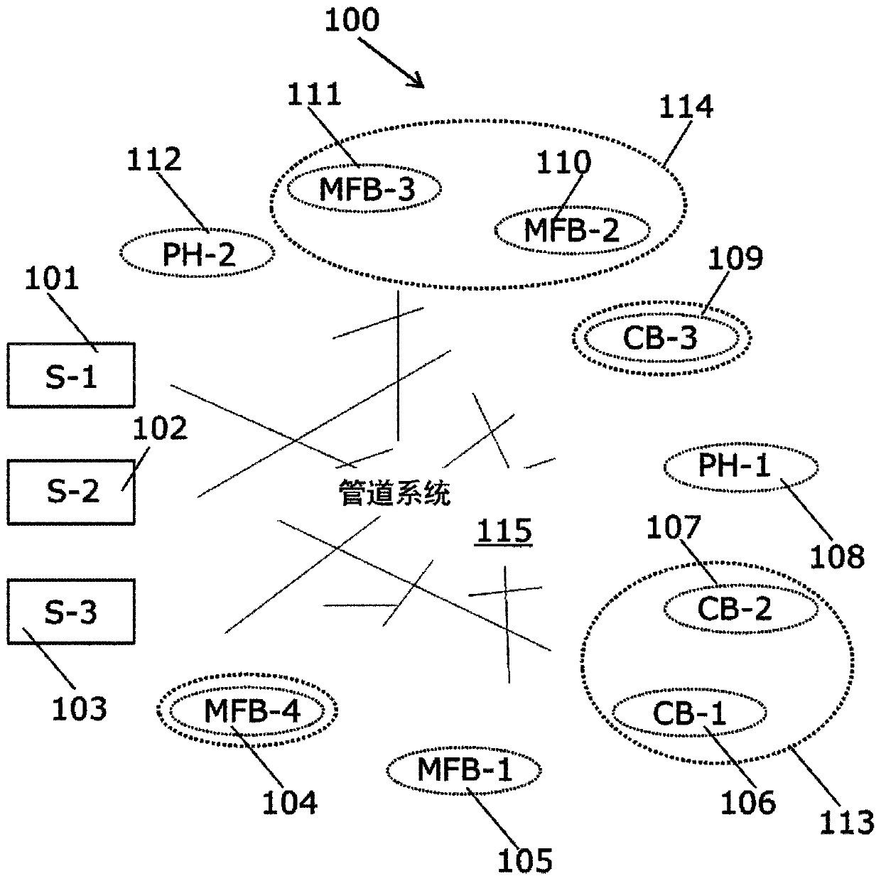
[0048] figure 1 Shown is a heating network 100 according to an embodiment of the invention, said heating network 100 comprising a supply side and a consumer side. The supply side comprises three supply devices 101, 102, 103 and the consumer side comprises a plurality of consumers 104-112. Some of the consumers are grouped into groups 113, 114 based on their behavior details and energy usage profiles. The supply side and the plurality of consumers 104-112 are interconnected by a piping system 115 which transports thermal energy from the supply devices 101-103 to the consumers 104-112.

[0049] The supply devices 101 - 103 are arranged to supply thermal energy to the heating network 100 , ie to a plurality of consumers 104 - 112 arranged to consume thermal energy from the heating network 100 . Each supply device 101-103 is connected to a piping system 115 which then delivers thermal energy directly to a plurality of consumers 104-112.

[0050] Optionally, the supply devices 1...


PUM


Abstract

The invention discloses a method for controlling the distribution of energy supply in a heating network (100) during peak loads (201, 2003). The heating network (100) includes a supply side and a consumer side configured to communicate with the supply side. At least one low-demand consuming equipment from multiple consuming equipment (104-112, 401, 402) is first identified, and then by controllingmass flow between the supply side and the identified one or more low-demand consuming equipment during the selected time period, for example, by reducing the differential pressure across the two endsof the differential pressure valve (408) at the connection between the supply side and the identified one or more low-demand consumption equipment, energy supply of the identified one or more low-demand consuming equipment is reduced. The energy supply to the remaining consumer equipment of the plurality of consumer equipment (104-112, 401, 402) is maintained during the selected time period.

Description

technical field [0001] The invention relates to a method for controlling the distribution of energy supply in a heating network, such as a heating or cooling network, during peak loads. Background technique [0002] Load variations in heating networks are a well-known challenge throughout the year, as variations occur daily and seasonally. Peaks in load variation are especially challenging because they lead to increased costs and failures on the heating network. The end-use load is usually the sum of the load for heating or cooling plus the load for domestic hot water production and network losses for all network users. Peak load is also the total load of peak loads and network losses of all customers over a relatively short period of time, and said peak load is usually much higher than the base load or average load that can be supplied by the heating network during normal operation many. [0003] The origin of peak loads lies in consumer behavior, weather conditions and ...

Claims


Application Information

Patent Timeline
Patent Type & Authority Applications(China)
IPC IPC(8): F24D19/10
CPCF24D19/1009F24D19/1048F24F11/62F24F11/83F24F11/70F24F11/46Y02P90/82Y02E20/14F24D10/003F24D12/02F25B29/003G06Q10/06
Inventor 米兰·姜吉克达斯克·夫那瑟克
Owner DANFOSS AS
Why Eureka
Try Eureka