Check patentability & draft patents in minutes with Patsnap Eureka AI!

Low-distortion moving coil framework structure of electric vibration table

A technology of electric vibration table and skeleton structure, which is applied in vibration testing, testing of machine/structural components, measuring devices, etc. It can solve the problems of affecting the resonance frequency of the moving coil, reducing the surface resonance of the moving coil, and complex processes, etc. The effect of reducing the distortion of the coil waveform, reducing the vibration noise of the moving coil, and simple processing technology

Pending Publication Date: 2020-06-02
SUZHOU SUSHI TESTING INSTR CO LTD
View PDF0 Cites 0 Cited by
  • Summary
  • Abstract
  • Description
  • Claims
  • Application Information

AI Technical Summary

Problems solved by technology

[0004] 1. Increase the thickness of the rib plate and the table top, but this method will increase the quality of the moving coil skeleton and affect the resonance frequency of the moving coil;
[0005] 2. Create a pit structure on the moving coil table, add foam material in the pit to increase the damping. On the one hand, this method affects the rigidity of the structure and the process is complicated. On the other hand, this method can only reduce the dynamic The resonance on the ring surface cannot reduce the resonance generated by the rib plate
[0006] Therefore, there are still certain defects in the existing processing methods for reducing resonance, reducing distortion, and reducing noise of the moving coil skeleton structure

Method used


Image

  • Low-distortion moving coil framework structure of electric vibration table
  • Low-distortion moving coil framework structure of electric vibration table
  • Low-distortion moving coil framework structure of electric vibration table

Examples


Embodiment Construction

[0025] The preferred embodiments of the present invention will be described in detail below in conjunction with the accompanying drawings, so that the advantages and features of the present invention can be more easily understood by those skilled in the art, so as to define the protection scope of the present invention more clearly.

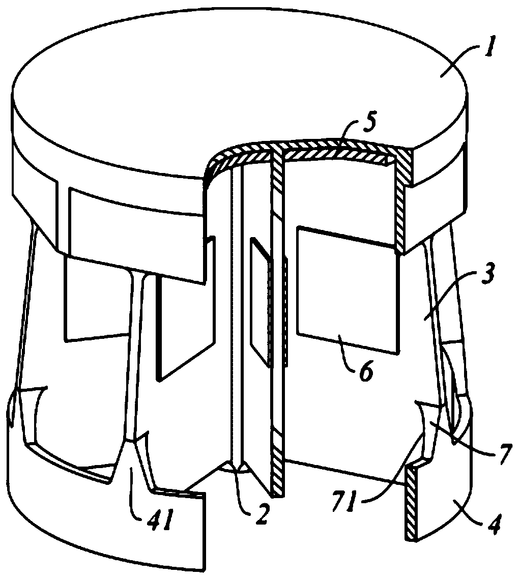
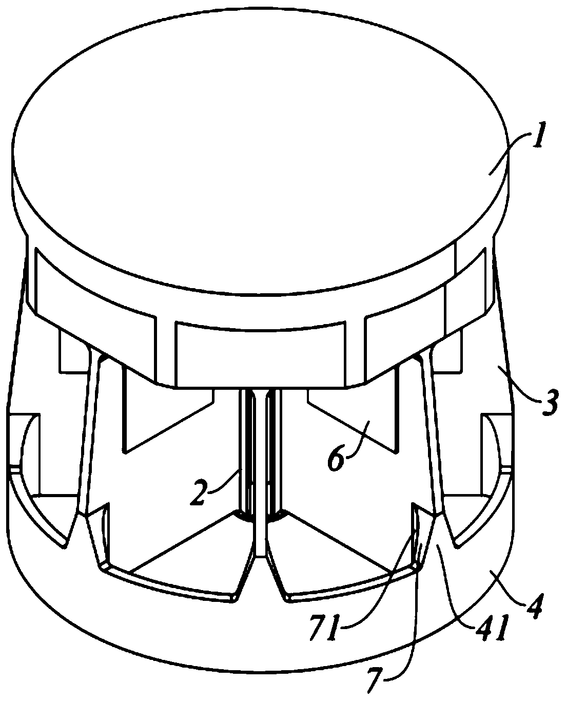
[0026] Please refer to Figure 1~4 , the present invention includes:

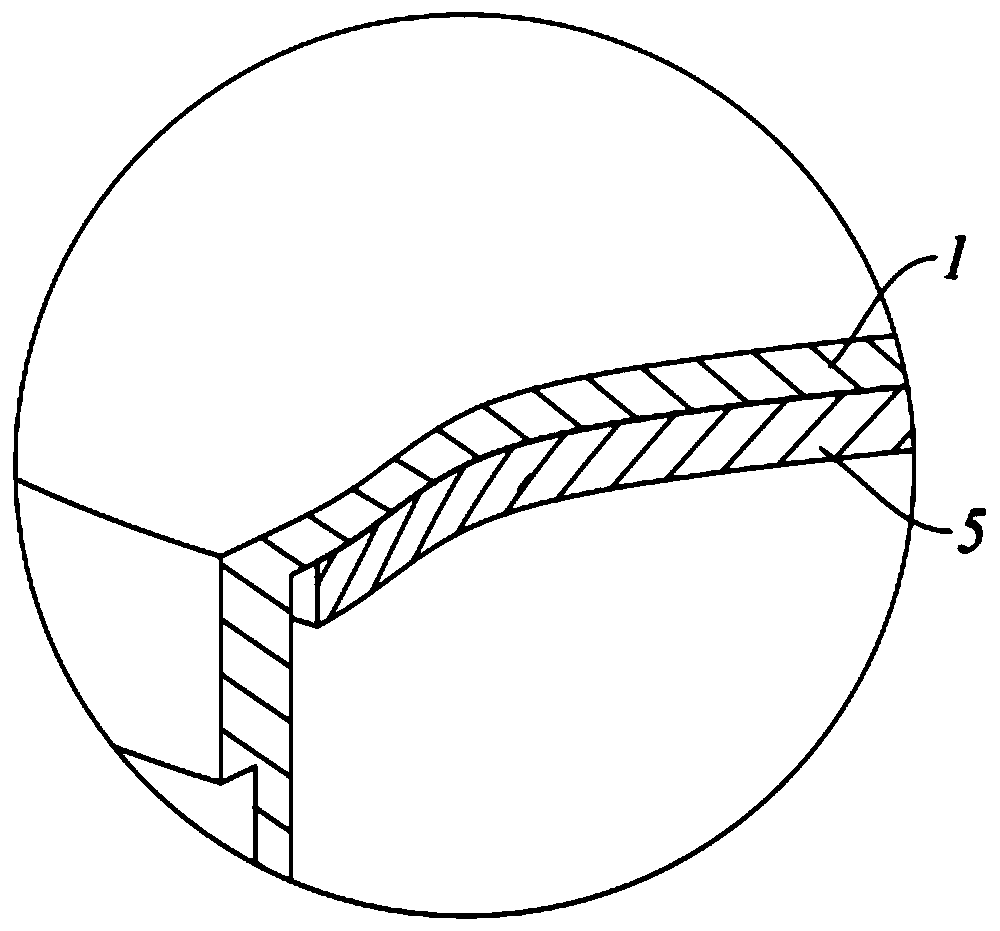
[0027] A low-distortion moving coil skeleton structure for an electric vibrating table, comprising: a table top 1, a center column 2, ribs 3, and skirt boards 4, wherein multiple ribs 3 are connected between the table top 1 and the skirt board 4 and centered on The columns 2 are evenly distributed in the center, the lower surface of the table 1 is pasted with a damping plate 5 , and the left and right side walls of the rib plate 3 are symmetrically pasted with damping blocks 6 .

[0028] Wherein, the damping plate 5 has several pieces uniformly distributed around the central ...


PUM


Abstract

The invention discloses an low-distortion moving coil framework structure of an electric vibration table, and the structure comprises a table top, a center column, rib plates and skirt plates; the ribplates are connected between the table top and the skirt plates and are evenly distributed with the center column as the center; damping plates are attached to the lower surface of the table top, anddamping blocks are symmetrically attached to the left side walls and the right side walls of the rib plates. In this way, the damping plates are attached to the lower surface of the table top, and the damping blocks are symmetrically attached to the left side wall and the right side wall of the rib plates, so the resonance generated at the table top and the rib plates of the moving coil can be eliminated so as to reduce the waveform distortion degree of the moving coil; meanwhile, the damping plates are attached to the inner top wall of the cavity formed by the table top and the rib plates ofthe moving coil, so the vibration noise of the moving coil can be reduced; in addition, the damping plates and the damping blocks are directly attached through glue, so the machining process is simple, and the manufacturing cost is low.

Description

technical field [0001] The invention relates to the field of moving coils of electric vibrating tables, in particular to a skeleton structure of low-distortion moving coils of electric vibrating tables. Background technique [0002] The electric vibration table can simulate various vibration dynamic environments, and is widely used in simulation tests of various typical vibrations such as auto parts, electronic components, and stress screening of aerospace products. The electric vibrating table is mainly composed of a moving coil assembly, a magnetic circuit assembly, a support assembly, a lower guide assembly, an upper guide assembly, an upper cover assembly, a lower cover assembly, and a support. [0003] The moving coil is the core component of the vibrating table, and its main technical requirements are: high rigidity, light weight, maximum mass-to-stiffness ratio, high resonance frequency, and low distortion. Among them, the moving coil skeleton in the moving coil is t...

Claims


Application Information

Patent Timeline
IPC IPC(8): G01M7/02
CPCG01M7/02
Inventor 朱江峰周华明赵斌
Owner SUZHOU SUSHI TESTING INSTR CO LTD
Features
  • R&D
  • Intellectual Property
  • Life Sciences
  • Materials
  • Tech Scout
  • Unparalleled Data Quality
  • Higher Quality Content
  • 60% Fewer Hallucinations
Learn More