Tool path planning method of five-axis parallel machining robot

A tool path and robot technology, applied in the field of robots, can solve the problems of reducing machining accuracy and machining efficiency, reducing tool swing angle motion speed, increasing the number of tool path curve segments, etc., so as to improve continuity, improve machining accuracy and machining efficiency. Effect

Active Publication Date: 2020-06-05
TSINGHUA UNIV
View PDF5 Cites 10 Cited by
  • Summary
  • Abstract
  • Description
  • Claims
  • Application Information

AI Technical Summary

Problems solved by technology

The smoothing method of curve fitting is usually used to fit short straight line segments to obtain a smooth spline processing path. However, the continuity between the spline curve and the adjacent path is difficult to guarantee, and the , the processing path is usually a mixed path of long straight line segment and short straight line segment group, directly performing curve fitting and smoothing will cause excessive fitting error and affect the processing accuracy
The local transition smoothing method inserts a transition curve at the connection point of the adjacent path to achieve a smooth transition of the machining path, which will increase the number of tool path curve segments and cause a great burden on the memory of the control system, and the transition segment Curvature will seriously restrict the processing feed rate and affect the processing efficiency
[0005] The five-degree-of-freedom parallel processing robot usually uses azimuth and swing angle (T&T angle) to describe its tool attitude, but there is a singular point in the expression of T&T angle, and the curve fitting and smoothing of the tool attitude directly in the T&T angle plane will lead to motion distortion. Reduce the speed of the tool swing angle, reduce the processing accuracy and processing efficiency

Method used


Image

  • Tool path planning method of five-axis parallel machining robot
  • Tool path planning method of five-axis parallel machining robot
  • Tool path planning method of five-axis parallel machining robot

Examples


Embodiment Construction

[0046] The following will clearly and completely describe the technical solutions in the embodiments of the present invention with reference to the accompanying drawings in the embodiments of the present invention. Obviously, the described embodiments are only some, not all, embodiments of the present invention. Based on the embodiments of the present invention, all other embodiments obtained by persons of ordinary skill in the art without making creative efforts belong to the protection scope of the present invention.

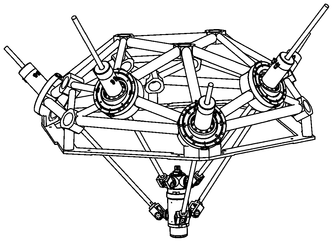
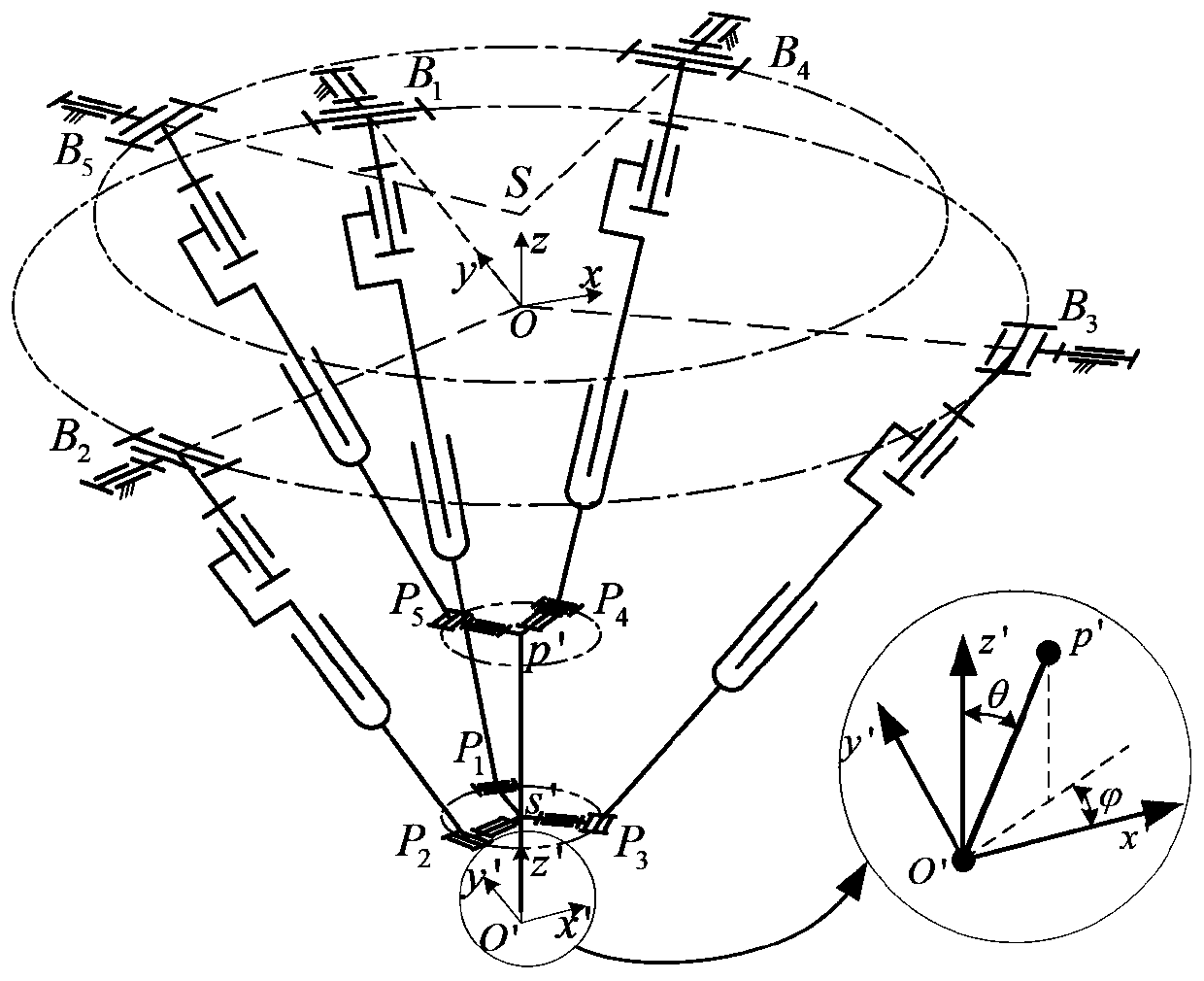
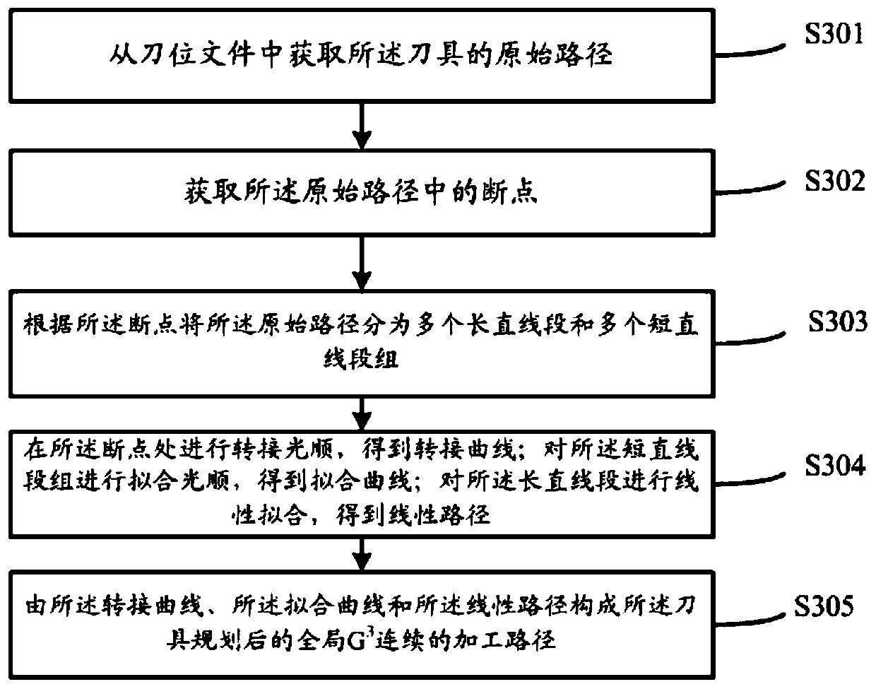
[0047] The object of the present invention is to provide a tool path planning method for a five-axis parallel machining robot, which can improve the continuity of the machining path of the tool of the robot, and further improve the machining accuracy and efficiency of the robot.

[0048] In order to make the above objects, features and advantages of the present invention more comprehensible, the present invention will be further described in detail below in con...


PUM


Abstract

The invention relates to a tool path planning method of a five-axis parallel machining robot. The method comprises the steps that an original tool path is obtained from a tool location file; break points in the original path are obtained; according to the break points, the original path is divided into multiple long straight line segments and multiple short straight line segment groups; transfer fairing is carried out on the break points, fitting fairing is carried out on the short straight line segment groups, and linear fitting is carried out on the long straight line sections; and a plannedoverall G3 continuous machining path of a tool is formed by a transfer curve formed after transfer fairing, a curve formed by the short straight line segment groups subjected to fitting fairing and alinear path formed by the long straight line segments subjected to linear fitting. By means of the tool path planning method of the five-axis parallel machining robot, continuity of the machining path of the tool of the robot can be improved, and therefore machining precision and machining efficiency of the robot are improved.

Description

technical field [0001] The invention relates to the field of robots, in particular to a tool path planning method for a five-axis parallel processing robot. Background technique [0002] In recent years, with the continuous improvement of mechanical design level, the design of parts has become more and more complex. Such parts usually have complex surface features, high dimensional accuracy and surface quality requirements. To realize the processing of such parts, the processing equipment should have the ability of compound angle processing and efficient processing. Compared with the traditional serial processing equipment, the parallel robot realizes the transmission of motion and force through multiple branch chains between the moving platform and the fixed platform. It has the advantages of compact structure, high rigidity, flexible movement, and good dynamic characteristics. Ideal for complex component machining. [0003] When this type of parallel robot is put into pr...

Claims


Application Information

Patent Timeline
Patent Type & Authority Applications(China)
IPC IPC(8): B25J9/16
CPCB25J9/16B25J9/1664
Inventor 谢福贵刘辛军解增辉汪劲松
Owner TSINGHUA UNIV
Why Eureka
Try Eureka