Self-inflating constant-pressure tire burst prevention system

A blow-flat and self-inflating technology, applied in the field of machinery, can solve problems such as blow-out accidents, and achieve the effects of not occupying space, avoiding blow-out accidents, and ensuring life safety.

Active Publication Date: 2020-06-05
浙江福林国润汽车零部件有限公司 +1
View PDF22 Cites 0 Cited by
  • Summary
  • Abstract
  • Description
  • Claims
  • Application Information

AI Technical Summary

Problems solved by technology

[0007] The purpose of the present invention is to solve the above-mentioned problems in the existing technology, and propose a self-inflating constant pressure anti-run-out tire system. The technical problem to be solved by the present invention is: how to solve the problem of tire blowout accidents caused by abnormal tire pressure

Method used


Image

  • Self-inflating constant-pressure tire burst prevention system
  • Self-inflating constant-pressure tire burst prevention system
  • Self-inflating constant-pressure tire burst prevention system

Examples


Embodiment 1

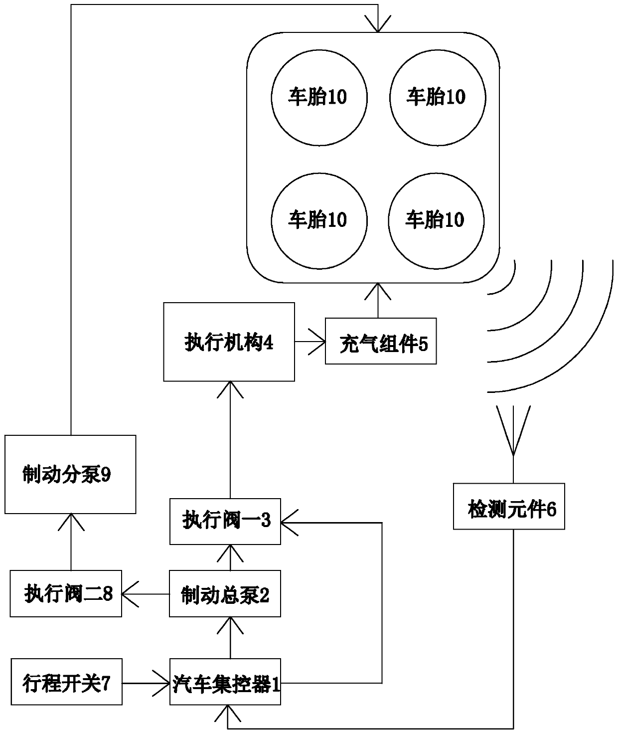
[0041] Such as Figure 1-3 As shown, the self-inflating constant pressure run-flat tire system includes a vehicle centralized controller, an actuator 4, a detection assembly 6 for detecting the tire pressure of each tire 10 of the vehicle, and an inflation assembly 5 fixed on each tire 10 of the vehicle. The vehicle centralized controller is an on-board ECU, and the detection component 6 includes a pressure sensor for detecting tire pressure and a receiver for receiving signals sent by the pressure sensor, and the receiver is electrically connected with the vehicle centralized controller.

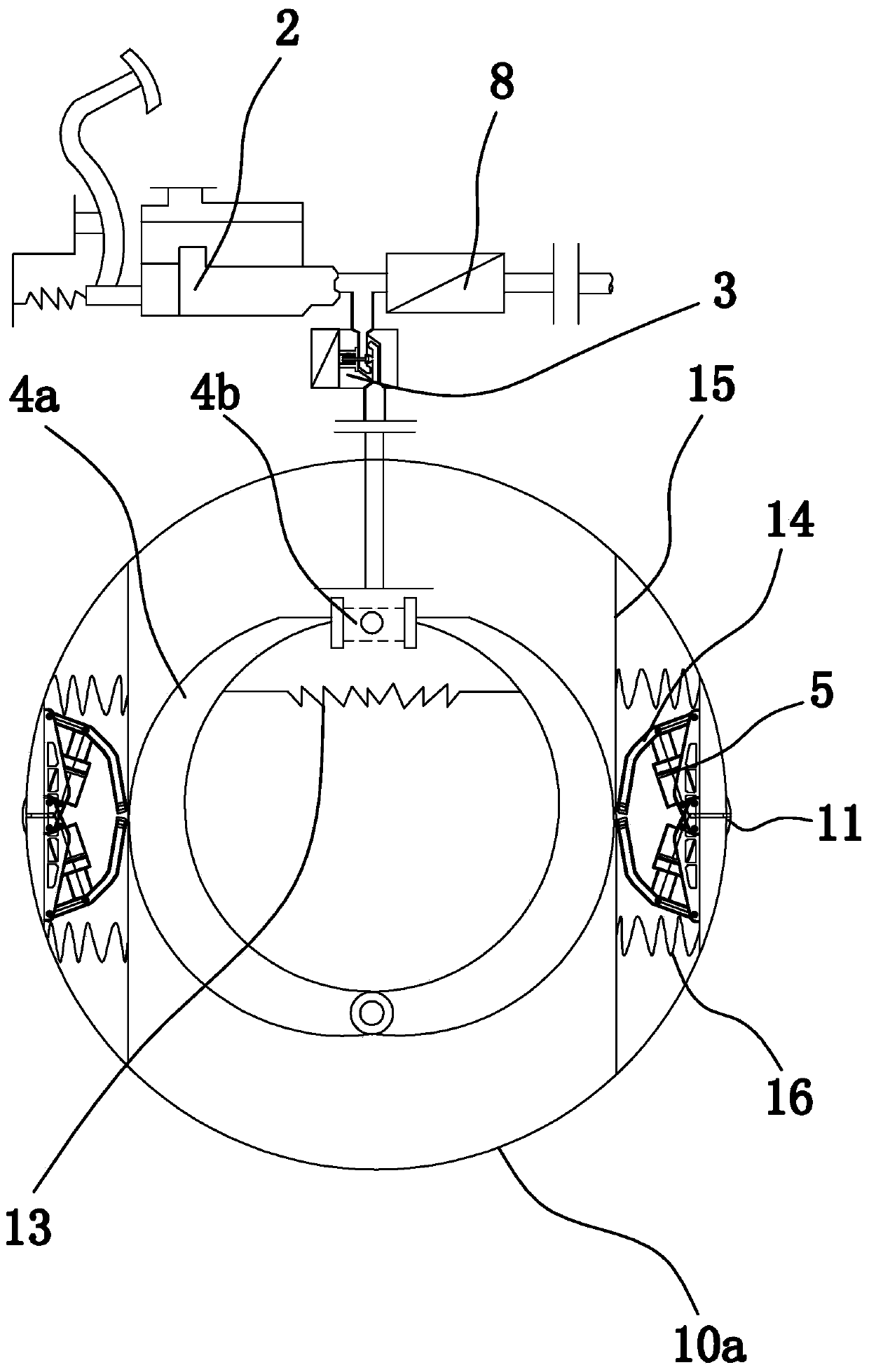
[0042] Specifically, each tire 10 is provided with two groups of inflatable components 5 , which are arranged symmetrically near the two sides of the corresponding wheel hub 10 a , and each group of inflatable components 5 includes at least two inflatable components 5 . In this embodiment, two inflatable assemblies 5 form a group. Each inflatable assembly 5 has a cylinder body 5a and a pis...

Embodiment 2

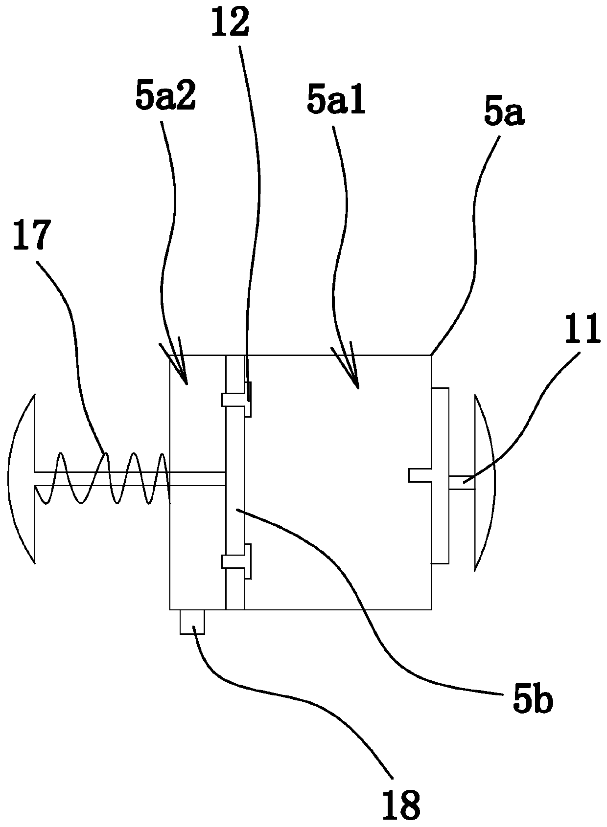
[0048] The structure of this embodiment is basically the same as that of Embodiment 1, the difference is: Figure 4 As shown, each group of inflatable components 5 includes an inflatable component 5, and a smooth pressurization guide plate 15 is also provided between each set of inflatable component 5 and the corresponding lever pressure bridge 4a. The hubs 10a are all connected by return springs 16. The piston 5b of the inflatable assembly 5 has a piston rod with one end protruding out of the cylinder body 5a. Swing outwards can be pressed on the steady pressure guide plate 15, and a return spring 17 that always makes the piston rod have a tendency to move outside the cylinder body 5a is also provided between the piston rod and the cylinder body 5a.

[0049] The detection component 6 sends the wheel pressure dynamics to the vehicle centralized controller in real time. The vehicle centralized controller performs real-time dynamic analysis and detection. When it is analyzed tha...

Embodiment 3

[0051] The structure of this embodiment is basically the same as that of Embodiment 1, the difference is: Figure 5 As shown, the actuator 4 includes two semicircular lever pressure bridges 4a. The middle parts of the two lever pressure bridges 4a are connected by a hydraulic part 4b that can push the two lever pressure bridges 4a to move relatively. Between and through one end, the piston 5b corresponding to the inflatable component 5 can be pushed to slide. The hydraulic component 4b can push the two lever pressure bridges 4a to move relative to each other, thereby pushing the corresponding piston 5b to slide to inflate, that is, to perform automatic inflation through the center expansion and opening.


PUM


Abstract

The invention provides a self-inflating constant-pressure tire burst prevention system, and belongs to the technical field of machinery. The tire burst prevention system solves the problem that an existing tire burst prevention system cannot avoid tire burst accidents due to the fact that the reserve amount of gas is limited. The self-inflating constant-pressure tire burst prevention system comprises a vehicle centralized controller, an execution mechanism, a detection assembly and inflation assemblies fixed to all tires of a vehicle. The detection assembly is electrically connected with the vehicle centralized controller; the inflation assembly comprises a cylinder body and a piston connected into the cylinder body in a sliding mode. An inner cavity of the cylinder body is divided into acompression cavity and an air inlet cavity communicated with the outside by the piston; the cylinder body is fixed on a hub of a corresponding tire, the compression cavity is communicated with the corresponding tire through an inflation one-way valve, the piston is further provided with an air inlet one-way valve which is communicated with the air inlet cavity and the compression cavity in a one-way mode, and the actuating mechanism is electrically connected with the vehicle centralized controller and can control the piston to slide back and forth. According to the system, early warning and control are combined with elimination of dangerous case relevance protocols, tire burst accidents are avoided, and the life safety of passengers is guaranteed.

Description

technical field [0001] The invention belongs to the technical field of machinery and relates to a self-inflating constant pressure run-flat tire system. Background technique [0002] As we all know, the "puncture" in most cases is often caused by tire underpressure or overpressure. When the air pressure does not meet the standard requirements, because the tire air pressure is too low, the sinking of the wheel increases, the radial deformation increases, the friction between the tread and the ground increases, the rolling resistance increases, and the internal stress of the carcass also increases, resulting in The temperature of the carcass rises sharply, and the tread rubber is wavy and flexes rapidly. Over time, the rubber becomes soft, which promotes the rapid aging of the tire, causing local delamination of the carcass and increased tread wear. In this case, if the car is still running at high speed on the expressway, the above-mentioned reaction of the tire will be acce...

Claims


Application Information

Patent Timeline
Patent Type & Authority Applications(China)
IPC IPC(8): B60C23/00B60C23/04B60C23/10
CPCB60C23/004B60C23/04B60C23/10
Inventor 管军荣
Owner 浙江福林国润汽车零部件有限公司
Why Eureka
Try Eureka