Textile fabric automatic discharging and spreading device

A textile cloth and automatic blanking technology, which is applied in the cutting of textile materials, textile and papermaking, thin material processing, etc., can solve the problems of inability to realize continuous automatic cloth spreading and low degree of automation, and achieve good cutting effect, The effect of quick cutting

Active Publication Date: 2020-06-05
沅江市凯祥纺织有限公司
View PDF10 Cites 10 Cited by
  • Summary
  • Abstract
  • Description
  • Claims
  • Application Information

AI Technical Summary

Problems solved by technology

[0004] Although the above-mentioned patent document discloses an automatic cloth spreading system applied to screen printin

Method used


Image

  • Textile fabric automatic discharging and spreading device
  • Textile fabric automatic discharging and spreading device
  • Textile fabric automatic discharging and spreading device

Examples


Embodiment 1

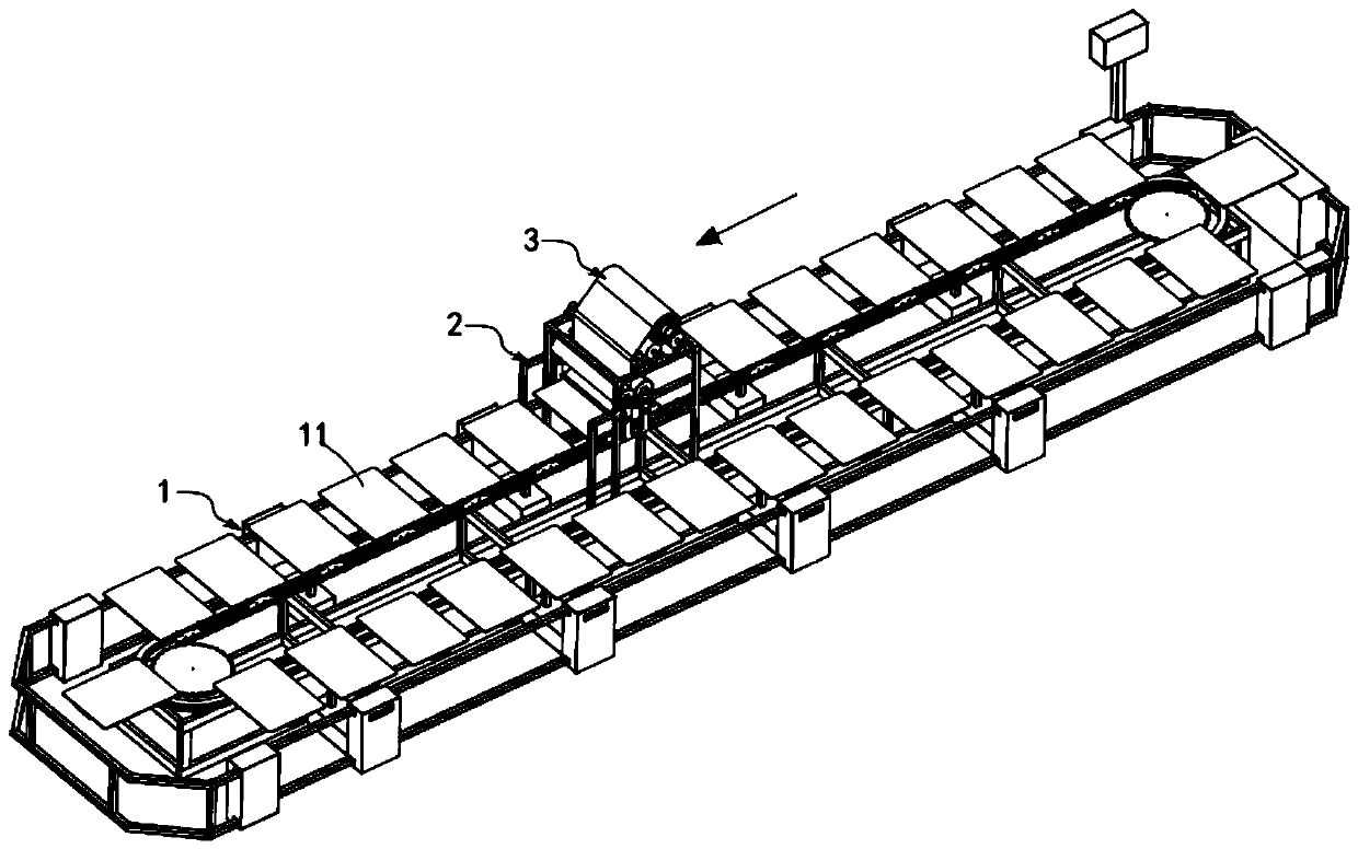
[0086] Such as Figure 1 to Figure 3 As shown, a kind of automatic unloading and laying device for textile fabrics includes a rotary conveying line 1, on which a number of spreading platforms 11 are equidistantly arranged, and the spreading platforms 11 are formed by the conveying line 1 drive rotary conveyor set, also includes:

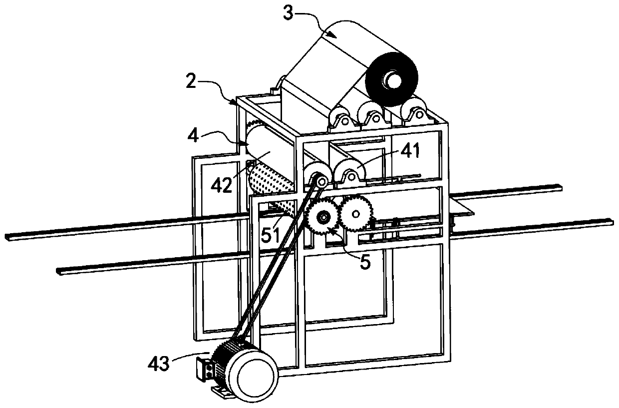
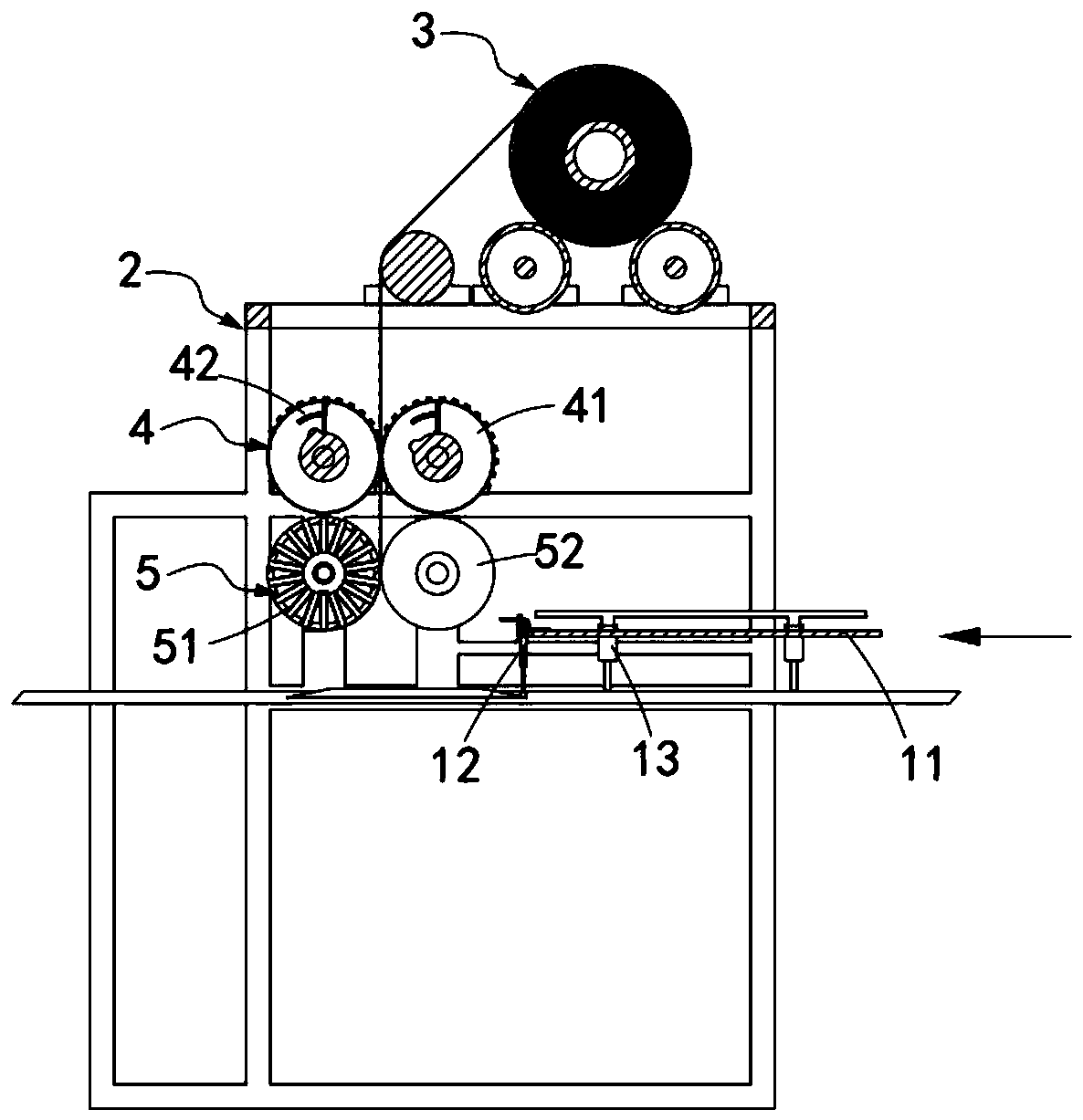
[0087] A material rack 2, the material rack 2 is arranged on the conveying path of the conveying line 1, the top of which is provided with a freely rotating textile fabric roll 3, and the axial direction of the textile fabric roll 3 crosses the length of the conveying line 1 Width direction setting;

[0088] Cutting mechanism 4, described cutting mechanism 4 is arranged on the below of described textile fabric roll 3, and it comprises cutting roller assembly 41, resisting roller assembly 42 and driving assembly 43, and described cutting roller assembly 41 and described resisting roller assembly 42 are all Set parallel to the textile fabric roll 3, ...

Embodiment approach

[0108] Such as Figure 11 to Figure 17 As shown, as a preferred embodiment, the resisting roller assembly 42 includes:

[0109] Collision with the outer roller 421, the interior of the collision outer roller 421 is hollow, and the outer circumference of the roller body is provided with a knife slot 4211;

[0110] The collision end cap 422 is used to block the openings at both axial ends of the collision outer roller 421;

[0111] The conflicting blade 423, the two ends of the conflicting blade 423 are slidably arranged in the sliding groove 4221 on the corresponding conflicting end cover 422, and a conflicting knife groove 4231 for interspersing with the cutting blade 413 is provided on it ;

[0112] The conflicting eccentric shaft 424, the conflicting eccentric shaft 424 coaxially passes through the conflicting outer roller 421, it is set in conflict with the conflicting blade 423, and it drives the conflicting blade 423 to slide to the insertion Sipe 4211; and

[0113] A...


PUM


Abstract

The invention relates to the technical field of garment fabric spreading machinery and specifically discloses a textile fabric automatic discharging and spreading device. The textile fabric automaticdischarging and spreading device comprises a conveying line, a rack, a cutting mechanism and an adsorption spreading mechanism. Fabric spreading boards are equidistantly conveyed on the conveying line. A textile fabric roll is erected on the rack. The cutting mechanism comprises a cutting roll assembly, a butting roll assembly and a driving assembly. The adsorption spreading mechanism comprises avacuum adsorption roll assembly and a clamping roll which are arranged in parallel. The textile fabric automatic discharging and spreading device automatically cuts the textile fabric roll through thecutting mechanism and spreads the cut textile fabric roll on the fabric spreading boards through the adsorption spreading mechanism. The technical problem of how to automatically spread the textile fabric roll onto the fabric spreading boards is solved. Meanwhile, the textile fabric automatic discharging and spreading device maintains the flatness of the textile fabric roll through the cutting roll assembly and the butting roll assembly in the cutting process and the spreading process.

Description

technical field [0001] The invention relates to the technical field of automatic tiling machinery for garment fabrics, in particular to an automatic unloading and tiling device for textile fabrics. Background technique [0002] The existing screen printing equipment applied to clothing fabrics is difficult to achieve continuous and fully automatic printing processing. It is necessary to manually fix the clothing fabrics to the screen printing table, and then move the clothing fabrics by the table. Screen printing processing is carried out directly below the screen, therefore, there is an urgent need for an automatic feeding and laying device for textile fabrics to realize automatic and flat laying of the platen. [0003] Patent No. CN201811067316.7 discloses a screen printing automatic spreading system, which specifically discloses a horizontal transmission device, a transmission unit, a lifting unit, a spreading roller, a printing platen, and a cloth releasing plate. The p...

Claims


Application Information

Patent Timeline
IPC IPC(8): B65H47/00B65H35/08B65H5/22D06H7/02
CPCB65H5/226B65H35/08B65H47/00D06H7/02
Inventor 金飞
Owner 沅江市凯祥纺织有限公司
Why Eureka
Try Eureka