an air flow sensor

An air flow and sensor technology, applied in electrical control, machine/engine, fuel injection control, etc., can solve the problems of engine oil intake and air intake mismatch, affect engine working efficiency, and fail to work normally, so as to achieve easy installation The effect of connection, simple structure and wide application range

Active Publication Date: 2022-06-24
武汉神动汽车电子电器股份有限公司
View PDF5 Cites 0 Cited by
  • Summary
  • Abstract
  • Description
  • Claims
  • Application Information

AI Technical Summary

Problems solved by technology

When the measured value of the air flow sensor is inaccurate, the fuel intake of the engine will not match the actual intake air, which will affect the working efficiency of the engine, and even fail to work properly in severe cases
The air flow sensor based on pressure detection has the characteristics of small size, high measurement accuracy, and wide measurement range. It is suitable for various types of engine air intake detection. The value is susceptible to deviation due to environmental factors, such as changes in geographical environment, changes in gas circulation area, etc.

Method used


Image

  • an air flow sensor
  • an air flow sensor
  • an air flow sensor

Examples


Embodiment Construction

[0026] The present invention will be further described in detail below with reference to the accompanying drawings, so that those skilled in the art can refer to the description and implement accordingly.

[0027] It should be noted that the experimental methods described in the following embodiments are conventional methods unless otherwise specified, and the reagents and materials can be obtained from commercial sources unless otherwise specified; in the description of the present invention, The terms "landscape", "portrait", "top", "bottom", "front", "rear", "left", "right", "vertical", "horizontal", "top", "bottom", The orientation or positional relationship indicated by "inside" and "outside" is based on the orientation or positional relationship shown in the accompanying drawings, which is only for the convenience of describing the present invention and simplifying the description, and does not indicate or imply that the indicated device or element must have The particul...


PUM


Abstract

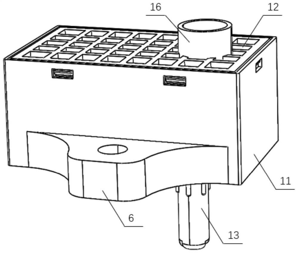
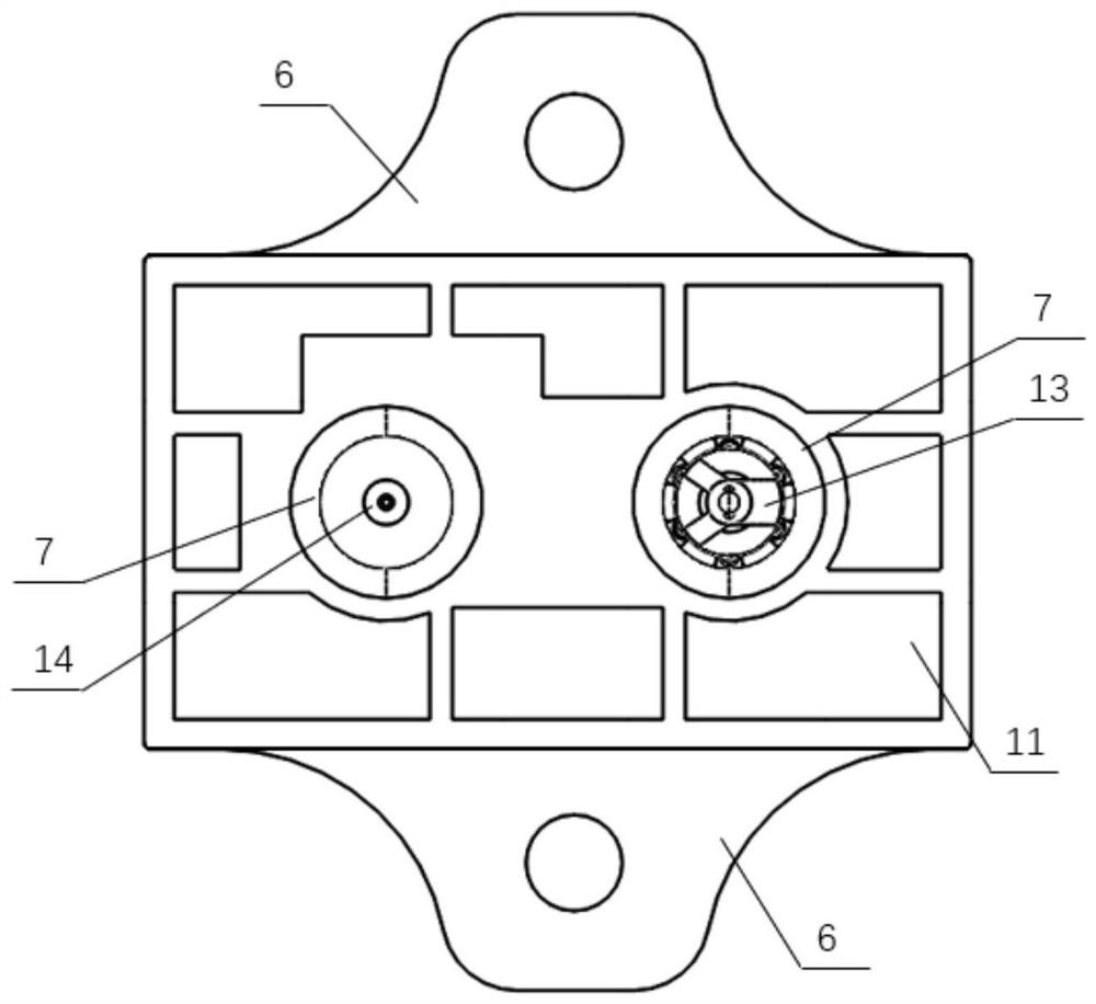
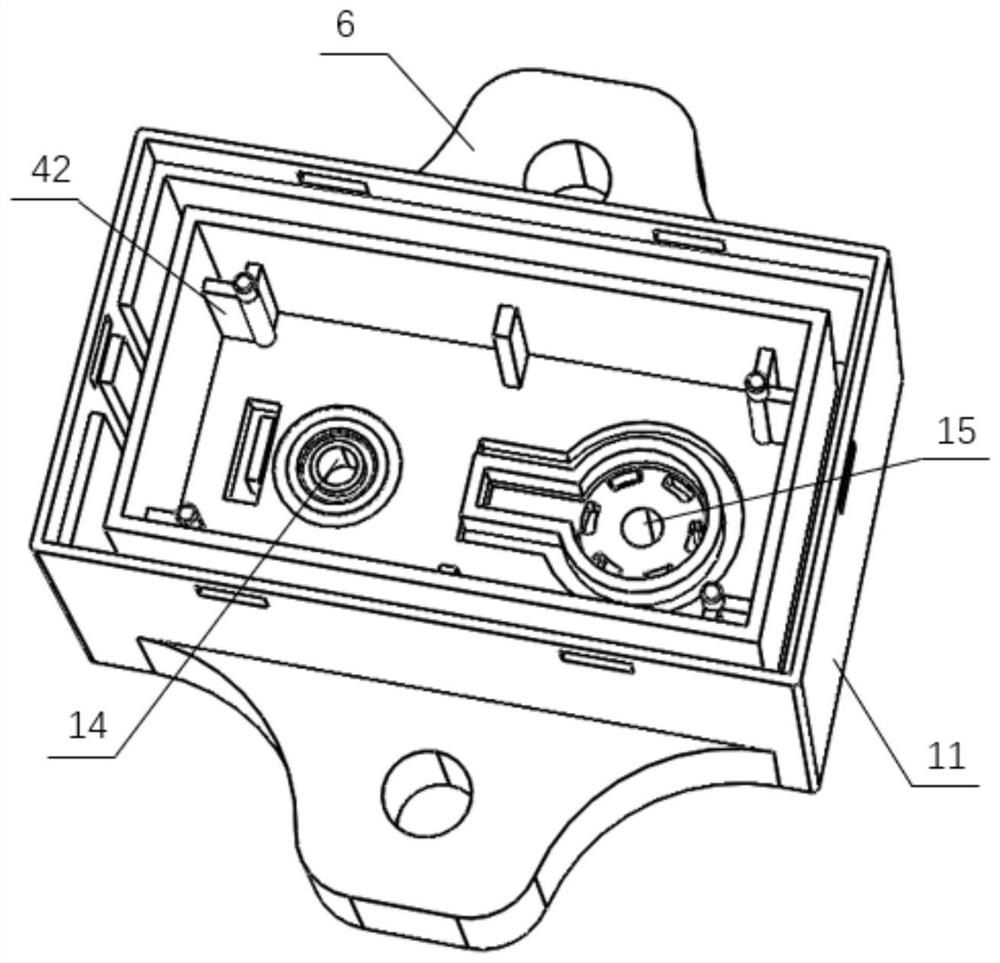
The invention discloses an air flow sensor, which comprises: a shell, including a shell, the bottom of which is provided with a through hole 1 and a through hole 2; an upper cover, which is arranged on the top of the shell and closed; The second air pipe passes through the first through hole and the second through hole respectively; the pressure sensor includes a ceramic substrate, which is fixed on the inner bottom surface of the housing and is provided with a positioning through hole, which is set directly opposite to the first through hole; The chip on the ceramic substrate includes a differential pressure chip, whose pressure sensing ends are respectively arranged on the top surface and the bottom surface; an absolute pressure chip, whose pressure sensing end is located on the top surface; two conditioning chips, which are respectively connected to the differential pressure chip and the absolute pressure chip Electrical connection; integrated circuit board, which is arranged above the pressure sensor and fixed to the inner side wall of the housing. The present invention realizes the stable measurement of the pressure parameters by arranging a differential pressure chip, an absolute pressure chip and a conditioning chip in cooperation with the internal structure, and calculates an accurate air flow rate after signal modulation.

Description

technical field [0001] The present invention relates to the field of gas flow sensors. More specifically, the present invention relates to an air flow sensor. Background technique [0002] The air flow sensor is an important device for measuring the intake air volume of the engine. According to its measurement value, the fuel intake volume of the engine is controlled to maintain the normal operation of the engine. When the measurement value of the air flow sensor is inaccurate, the fuel intake of the engine will not match its actual intake air, thereby affecting the working efficiency of the engine, and even cannot work normally in severe cases. The air flow sensor based on pressure detection has the characteristics of small size, high measurement accuracy and wide measurement range, and is suitable for the detection of air intake volume of various types of engines. The value is susceptible to deviations due to environmental factors, such as changes in geographical environ...

Claims


Application Information

Patent Timeline
Patent Type & Authority Patents(China)
IPC IPC(8): F02D41/18
CPCF02D41/18
Inventor 刘慧琳董秀辉艾稳姚渊
Owner 武汉神动汽车电子电器股份有限公司
Why Eureka
Try Eureka