Connecting device, pulverized coal burner sprayer assembly and assembly and replacement methods
A pulverized coal burner and connection device technology, applied in the direction of combustion method, burner for burning powder fuel, burner, etc., can solve problems such as connection and assembly difficulties, solve assembly and disassembly difficulties, facilitate positioning and installation, and reduce The effect of scrap rate
- Summary
- Abstract
- Description
- Claims
- Application Information
AI Technical Summary
Problems solved by technology
Method used
Image
Examples
Embodiment 1
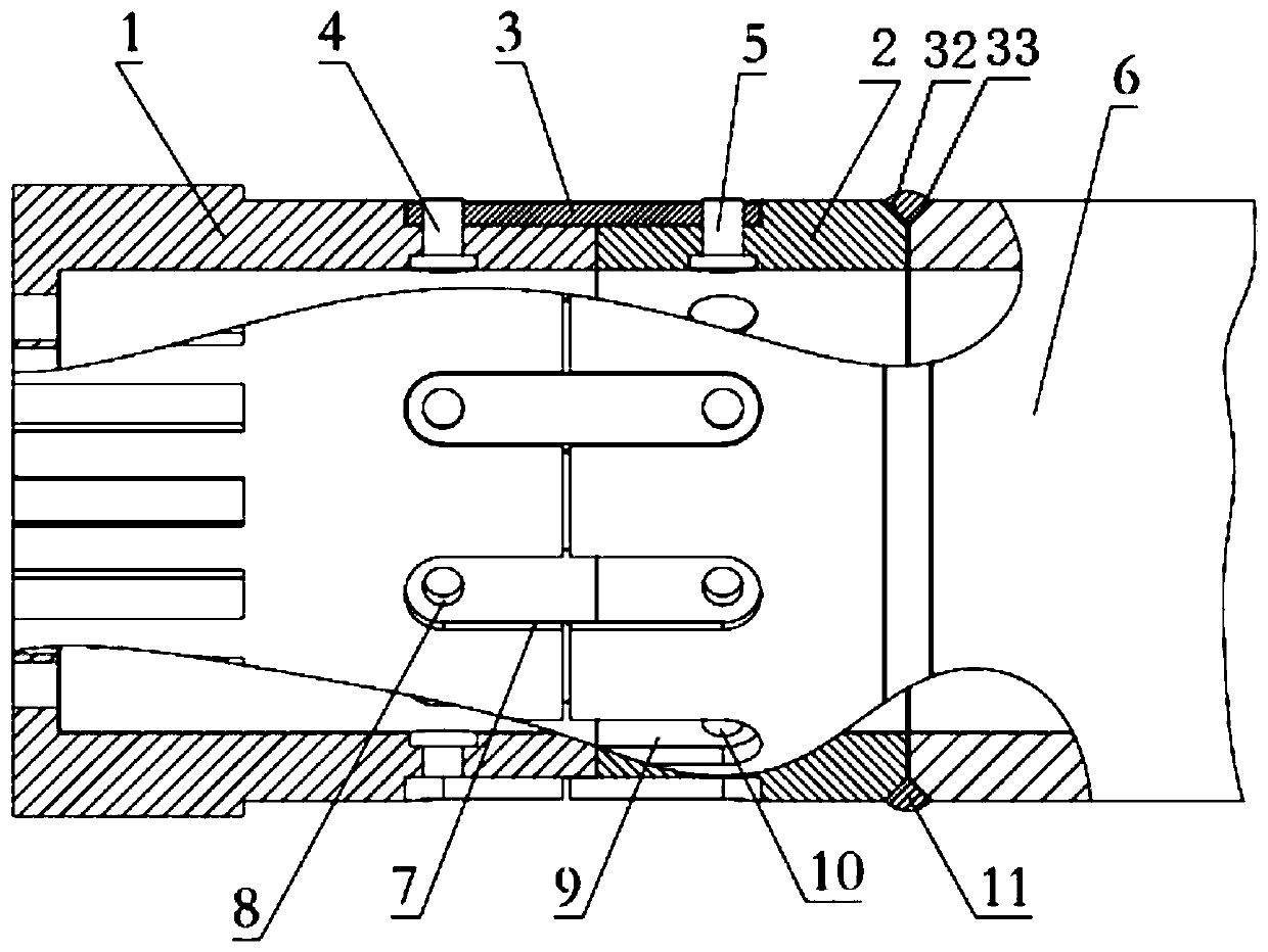
[0047] Such as figure 1 As shown, the connecting device provided in this embodiment is used to realize the pulverized coal burner nozzle 1 and the iron alloy body of the pulverized coal burner made of high-temperature and abrasion-resistant materials (for example, reaction sintered silicon carbide ceramic materials, alumina ceramic materials) The connection and assembly of the work piece 6 includes a ferroalloy connecting ring 2 with an outer diameter that matches the ferroalloy main body work piece 6, a plurality of ferroalloy cantilever connectors 3 with better elasticity arranged on the ferroalloy connecting ring 2, and used to realize the ferroalloy cantilever connector 3 The first fixing member 4 connected with the pulverized coal burner nozzle 1 and the second fixing member 5 for connecting the ferroalloy cantilever connecting member 3 and the ferroalloy connecting ring 2.
[0048] In order to facilitate the assembly and positioning, and make the structure compact after asse...
Embodiment 2
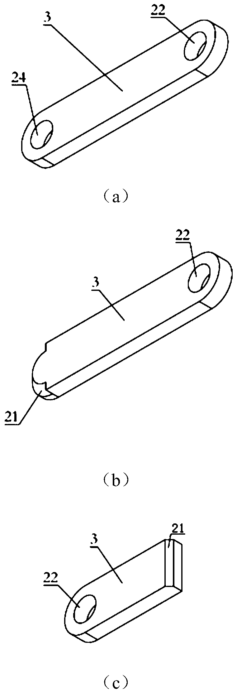
[0059] The difference between this embodiment and embodiment 1 is that only one end of the ferroalloy cantilever connector 3 is provided with a first fixing member assembly hole 22, and an arc-shaped welding groove 21 is machined on the upper surface of the other end, such as figure 2 As shown in (b); correspondingly, the second cantilever fixing hole 10 does not need to be machined in the second cantilever groove 9 on the ferroalloy connecting ring 2.
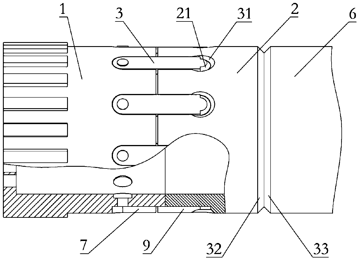
[0060] Such as image 3 As shown, the assembly process of this embodiment is basically the same as that of Embodiment 1, except that the other end of the ferroalloy cantilever connector 3 is welded into the second cantilever groove 9 of the ferroalloy connecting ring 2.
[0061] When the nozzle 1 of the pulverized coal burner needs to be replaced, the disassembly and replacement process of this embodiment is the same as that of the first embodiment.
Embodiment 3
[0063] The difference between this embodiment and embodiment 2 is only: the form of the welding groove 21 at the end of the ferroalloy cantilever connector 3 is different, such as figure 2 As shown in (c), in this embodiment, the welding groove 21 at the end of the ferroalloy cantilever connector 3 is a straight groove; correspondingly, the ferroalloy connecting ring 2 omits the second cantilever groove 9, but is in the ferroalloy connecting ring 2. The end of the welding groove 42 corresponding to the welding groove 21 is processed.
[0064] Such as Figure 4 As shown, the assembly process of this embodiment is basically the same as that of Embodiment 2, except that the other end of the ferroalloy cantilever connector 3 is directly welded to the end of the ferroalloy connecting ring 2.
[0065] This embodiment can only realize the replacement of the entire pulverized coal burner nozzle assembly, and the replacement method is the same as the first embodiment.
PUM
 Abstract
Description
Claims
Application Information
 - R&D
- Intellectual Property
- Life Sciences
- Materials
- Tech Scout
- Unparalleled Data Quality
- Higher Quality Content
- 60% Fewer Hallucinations
Browse by: Latest US Patents, China's latest patents, Technical Efficacy Thesaurus, Application Domain, Technology Topic, Popular Technical Reports.
© 2025 PatSnap. All rights reserved.Legal|Privacy policy|Modern Slavery Act Transparency Statement|Sitemap|About US| Contact US: help@patsnap.com


