Two-dimensional DOA estimation method based on L-shaped array

An array and L-shaped technology, which is applied in the field of array signal angle estimation, can solve problems such as unsolvable underdetermined problems and estimated signals, increased equipment complexity and cost, and complex structure of coprime arrays.

Active Publication Date: 2020-06-05
XIJING UNIV
View PDF7 Cites 6 Cited by
  • Summary
  • Abstract
  • Description
  • Claims
  • Application Information

AI Technical Summary

Problems solved by technology

However, when the number of signal sources is greater than the number of array elements in practical application scenarios such as ground radar and non-cooperative communication, traditional subspace methods need to extract noise subspace or signal subspace, and the signal subspace dimension The number must be smaller than the dimension of the covariance matrix of the received signal, so it is impossible to solve this kind of underdetermined problem and estimate the DOA of the signal
In order to effectively estimate the DOA of more sources and improve the estimation accuracy, it is usually necessary to increase the number of array elements in the actual array to expand the dimension of the covariance matrix of the received signal and the array aperture; however, the increase in the number of array elements is bound to bring engineering applications Increased equipment complexity and cost in
In order to solve the underdetermined problem under the limited number of array elements, some scholars proposed the concept of coprime array, but the characteristic that the distance between elements of coprime array is several times of half wavelength of the signal source leads to the problem of angular ambiguity in DOA estimation, and the interprime array The mass array structure is more complex

Method used


Image

  • Two-dimensional DOA estimation method based on L-shaped array
  • Two-dimensional DOA estimation method based on L-shaped array
  • Two-dimensional DOA estimation method based on L-shaped array

Examples


Embodiment Construction

[0053] The following will clearly and completely describe the technical solutions in the embodiments of the present invention with reference to the accompanying drawings in the embodiments of the present invention. Obviously, the described embodiments are only some, not all, embodiments of the present invention. Based on the embodiments of the present invention, all other embodiments obtained by persons of ordinary skill in the art without creative efforts fall within the protection scope of the present invention.

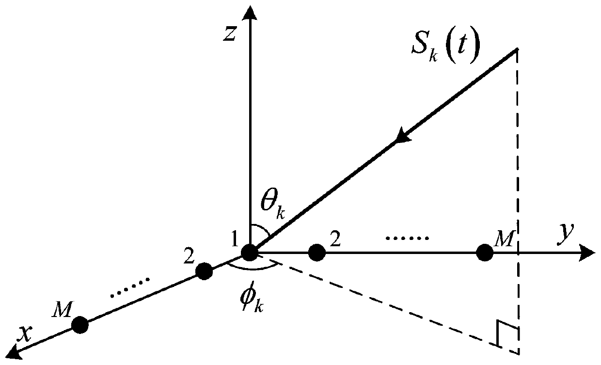
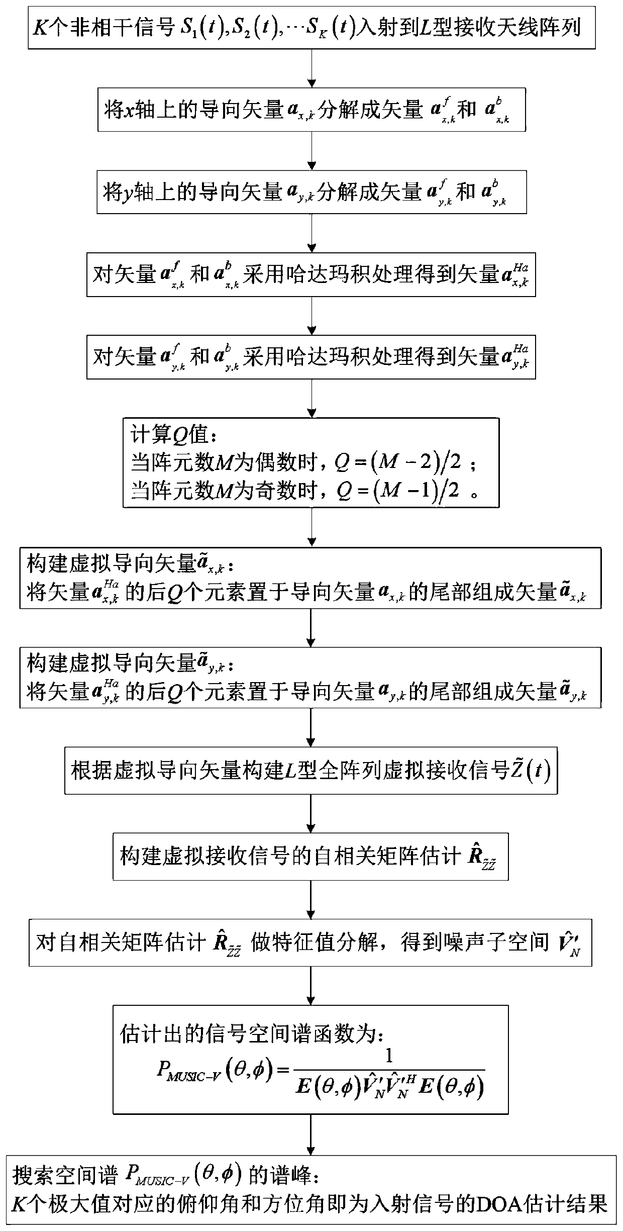
[0054] refer to Figure 1-2 : The present invention provides a kind of technical scheme: a kind of two-dimensional DOA estimation method based on L-shaped array, comprises the following steps:

[0055] Step 1: Establish a time-domain model of array reception;

[0056] Suppose K uncorrelated far-field narrowband signals S 1 (t),S 2 (t),...S K (t) by pitch angle θ k (k=1,2,...,K) and azimuth φ k (k=1,2,...,K) is incident on an L-shaped receiving antenna array a...


PUM


Abstract

The invention discloses a two-dimensional DOA estimation method based on an L-shaped array in the technical field of array signal angle estimation. The two-dimensional DOA estimation method comprisesthe following steps: 1, establishing a time domain model of array receiving; 2, decomposing an actual steering vector, and processing the decomposed vector by utilizing a Hadamard product; placing thelast Q elements of the vector processed by the Hadamard product at the tail of the actual steering vector to construct a virtual steering vector; 3, constructing estimation of a received signal autocorrelation matrix according to the virtual steering vector, and carrying out eigenvalue decomposition to obtain estimation of a noise subspace; and 4, constructing a spatial spectrum function, and estimating the DOA of the incident signal according to spectral peak search. The underdetermined problem that the number of signal sources to be estimated is greater than the number of physical array elements under the condition of limited array elements is effectively solved. The complexity and hardware cost of equipment in practical application are reduced, and the signal DOA estimation precision is effectively improved.

Description

technical field [0001] The invention relates to the technical field of array signal angle estimation, in particular to a two-dimensional DOA estimation method based on an L-shaped array. Background technique [0002] Direction of Arrival (DOA) estimation is an important research content in the field of array signal processing, and it is widely used in radar, wireless communication, sonar and other fields. The traditional subspace method is represented by the multiple signal classification (MUSIC) algorithm, which starts from the concept of linear space and realizes super-high resolution DOA estimation with excellent algorithm stability. However, when the number of signal sources is greater than the number of array elements in practical application scenarios such as ground radar and non-cooperative communication, traditional subspace methods need to extract noise subspace or signal subspace, and the signal subspace dimension The number must be smaller than the dimension of t...

Claims


Application Information

Patent Timeline
Patent Type & Authority Applications(China)
IPC IPC(8): G01S3/14
CPCG01S3/14Y02D30/70
Inventor 王薇马亚红范小娇张善文徐聪王旭启田笑成赵穆清
Owner XIJING UNIV
Why Eureka
Try Eureka