Interference signal suppression circuit and electrical device

A technology of interference signal and suppression circuit, applied in the direction of electrical components, output power conversion devices, etc., can solve the problem that electromagnetic interference signals cannot be completely suppressed or absorbed

Active Publication Date: 2020-06-05
GREE ELECTRIC APPLIANCES INC
View PDF9 Cites 4 Cited by
  • Summary
  • Abstract
  • Description
  • Claims
  • Application Information

AI Technical Summary

Problems solved by technology

[0005] The embodiment of the present invention provides an interference signal suppression circuit and electrical equipment to solve the problem that the electromagnetic interference signal generated inside the electrical equipment cannot be completely suppressed or absorbed in the prior art

Method used


Image

  • Interference signal suppression circuit and electrical device
  • Interference signal suppression circuit and electrical device
  • Interference signal suppression circuit and electrical device

Examples


Embodiment 1

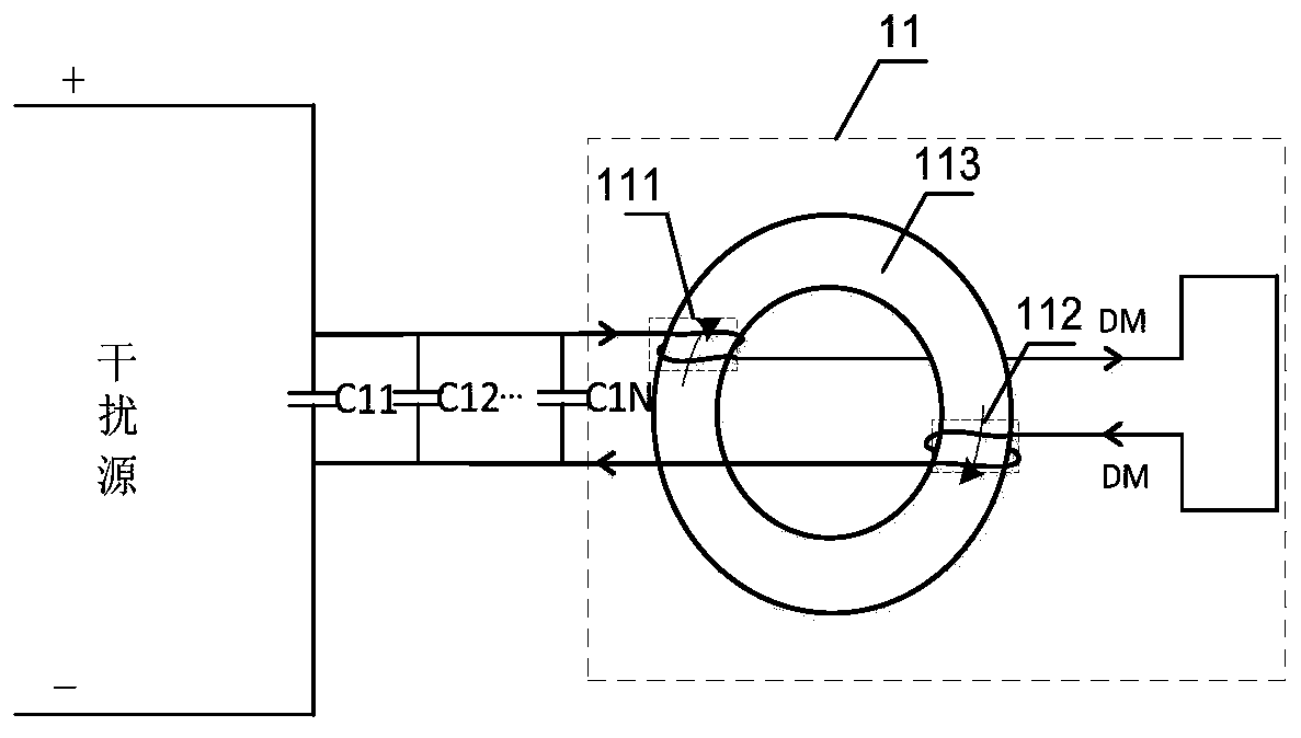
[0051] This embodiment provides an interference signal suppression circuit, figure 1 It is a structural diagram of an interference signal suppression circuit according to an embodiment of the present invention, such as figure 1As shown, the circuit is connected to the interference source in the electrical equipment, which includes: a primary filter capacitor C1, the first end of the primary filter capacitor C1 is connected to the first terminal of the interference source, and the second end is connected to the second terminal of the interference source. terminals, wherein the number of the primary filter capacitors can be 1, or two or more, and when the number of the primary filter capacitors C1 is two or more, each primary filter capacitor C1 After being connected in parallel, they are connected in series between the first terminal and the second terminal of the interference source. In this embodiment, N primary filter capacitors including C1, C1...C1N are included.

[0052]...

Embodiment 2

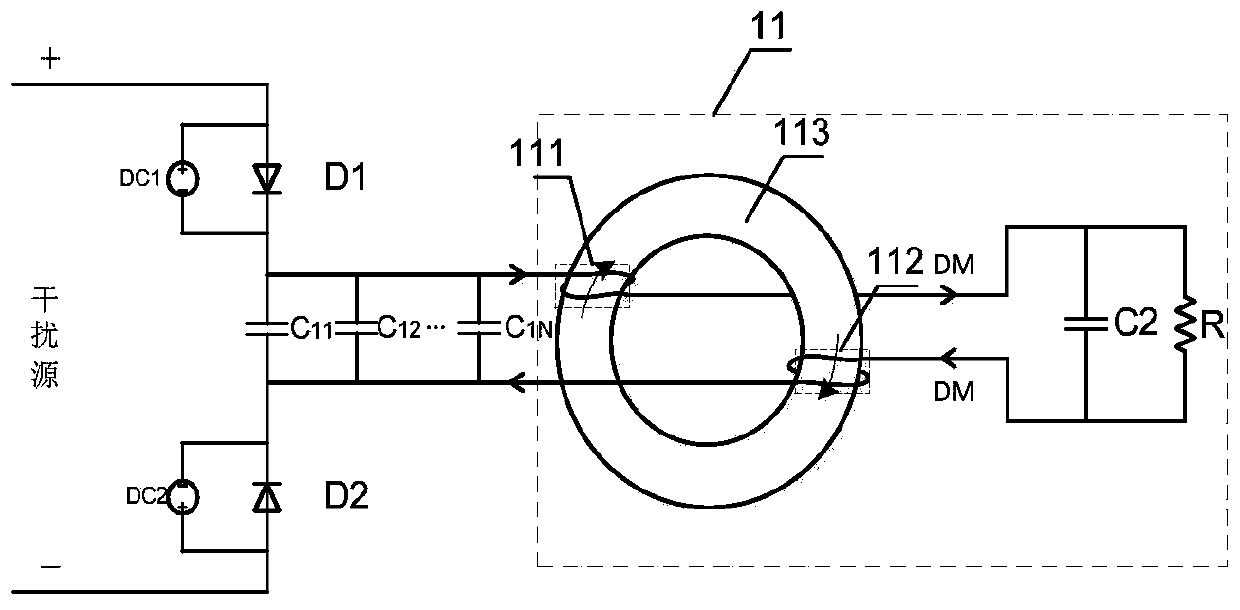
[0057] This embodiment provides another interference signal suppression circuit, image 3 It is a structural diagram of an interference signal suppression circuit according to another embodiment of the present invention. Since the ability to absorb and consume differential mode interference signals DM is weak only based on wires, as image 3 As shown, on the basis of the above embodiments, the differential mode signal loop 11 further includes: a secondary filter capacitor C2 connected in series to the output terminal of the first differential mode coil 111 and the second differential mode coil 112 Between the input terminals, it is used to quickly absorb the differential mode interference signal DM, so as to avoid diffusion to the external space.

[0058] As mentioned above, the ability of the wire to consume the differential mode interference signal DM is weak, so in order to enhance the ability to consume the differential mode interference signal DM, the differential mode si...

Embodiment 3

[0064] This embodiment provides another interference signal suppression circuit, Figure 4 It is a structural diagram of an interference signal suppression circuit according to another embodiment of the present invention. The interference signal suppression circuit in the above embodiment realizes the function of absorbing and consuming the differential mode interference signal DM generated by the interference source, but the interference source will also generate Common-mode interference signal CM, in order to eliminate the common-mode interference signal CM generated by the interference source, such as Figure 4 Said, on the basis of the above embodiments, the interference signal suppression circuit further includes: a first common mode choke coil 21 and a second common mode choke coil 22;

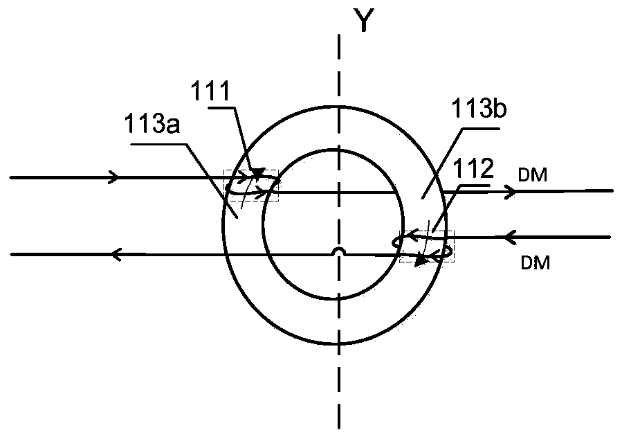
[0065] Figure 5 It is a structural schematic diagram of a magnetic ring according to another embodiment of the present invention, such as Figure 5 As shown, the magnetic ring is an e...


PUM


Abstract

The invention discloses an interference signal suppression circuit and an electrical device. The circuit comprises a primary filter capacitor, of which the first end is connected with a first terminalof an interference source, and the second end is connected with a second terminal of the interference source; a differential mode signal loop which comprises a first differential mode coil, a seconddifferential mode coil and a magnetic ring, wherein the first differential mode coil is wound in the first winding area of the magnetic ring, and the input end of the first differential mode coil is connected to the first end of the primary filter capacitor; the second differential mode coil is wound in the second winding area of the magnetic ring, the output end of the second differential mode coil is connected to the second end of the primary filter capacitor, and the output end of the first differential mode coil is connected with the input end of the second differential mode coil. According to the invention, the interference signals can be completely absorbed and eliminated.

Description

technical field [0001] The invention relates to the technical field of electronic circuits, in particular to an interference signal suppression circuit and electrical equipment. Background technique [0002] In modern power electronic frequency conversion technology, there are two parts of low voltage and high voltage. As the functions of electrical equipment become more and more complex, there are many types of power supplies in the low-voltage part, and the power is larger. At the same time, the requirements for miniaturization are increased, the control board is highly integrated, and the device density is increased, so it is easy for each device to interfere with each other. When the IGBT or MOS in the high-voltage part is turned on and off, strong voltage-type and current-type interference signals will be generated. It is easy to couple to other circuits through parasitic capacitance and parasitic inductance to cause electromagnetic interference (EMI, Electromagnetic ...

Claims


Application Information

Patent Timeline
Patent Type & Authority Applications(China)
IPC IPC(8): H02M1/12
CPCH02M1/126H02M1/123
Inventor 于洪涛杨湘木张煜文杨帆刘文斌
Owner GREE ELECTRIC APPLIANCES INC
Why Eureka
Try Eureka