
Harmful waste gas treatment equipment and treatment method

A technology for waste gas treatment and treatment method, applied in the field of harmful waste gas treatment equipment, can solve the problems of few organic waste gas and acidic waste gas purification methods, the inability to accurately predict the temperature and humidity relationship of waste gas, and the inability to detect various harmful gases, etc. Accurate monitoring of installation, outstanding absorption effect, and the effect of reducing workload

Pending Publication Date: 2019-07-23
驿涛工程集团有限公司
View PDF4 Cites 4 Cited by
  • Summary
  • Abstract
  • Description
  • Claims
  • Application Information

AI Technical Summary

Problems solved by technology

[0004] In the existing waste gas treatment process, the detection equipment for the waste gas flow consumes a lot of power, the measurement accuracy is low, and the range is narrow; at the same time, there are many existing researches on the removal of organic waste gas, but the purification method that can simultaneously remove organic waste gas and acid waste gas less
[0005] The detection accuracy of the existing harmful exhaust gas is not high, and at the same time the speed is slow; it is impossible to detect a variety of harmful gases
In the prior art, the relationship between exhaust gas temperature and humidity cannot be accurately predicted, resulting in unsatisfactory exhaust gas treatment effect

Method used


Image

  • Harmful waste gas treatment equipment and treatment method
  • Harmful waste gas treatment equipment and treatment method
  • Harmful waste gas treatment equipment and treatment method

Examples


Embodiment Construction

[0060] In order to further understand the invention content, features and effects of the present invention, the following embodiments are exemplified, and detailed descriptions are included with the accompanying drawings.

[0061] In the existing waste gas treatment process, the detection equipment for the waste gas flow consumes a lot of power, the measurement accuracy is low, and the range is narrow; at the same time, there are many existing researches on the removal of organic waste gas, but the purification method that can simultaneously remove organic waste gas and acid waste gas less. The detection accuracy of the existing harmful waste gas is not high, and at the same time, the speed is slow; it is impossible to detect a variety of harmful gases.

[0062] In order to solve the above problems, the structure of the present invention will be described in detail below in conjunction with the accompanying drawings.

[0063] Such as figure 1 As shown, the harmful exhaust ga...


PUM


Abstract

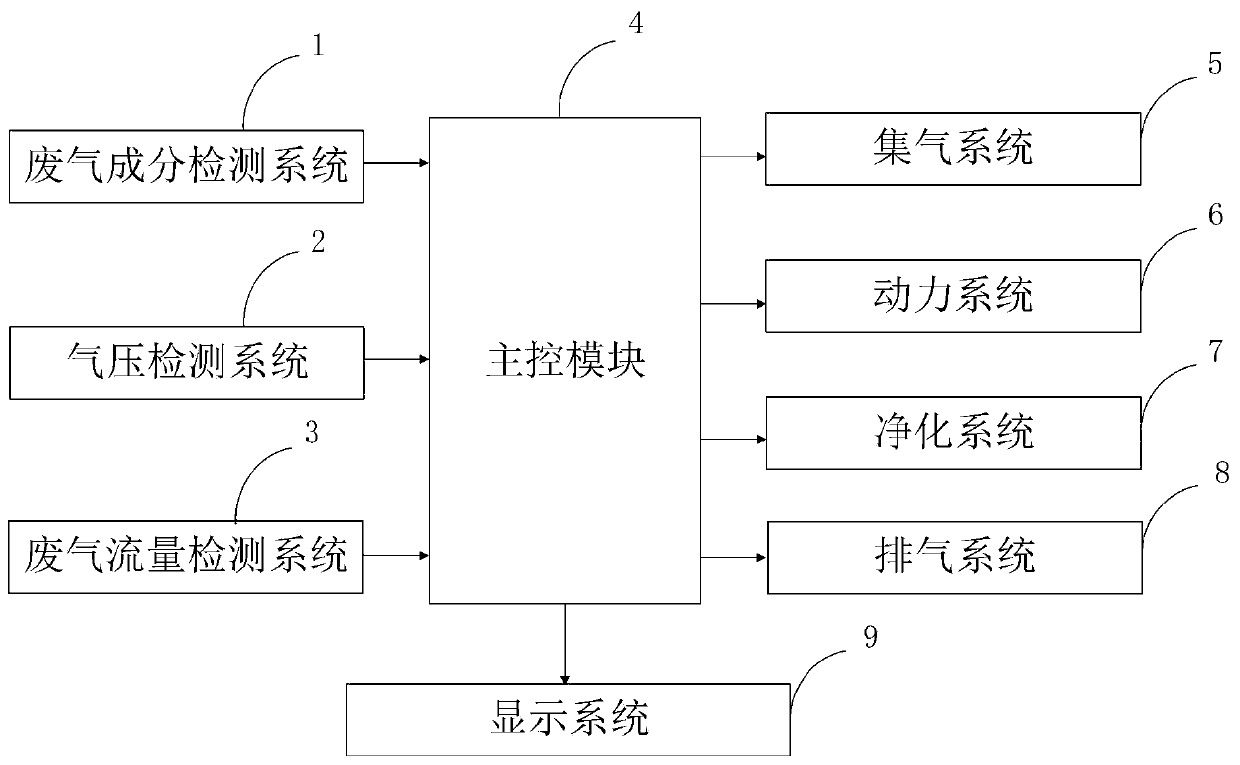
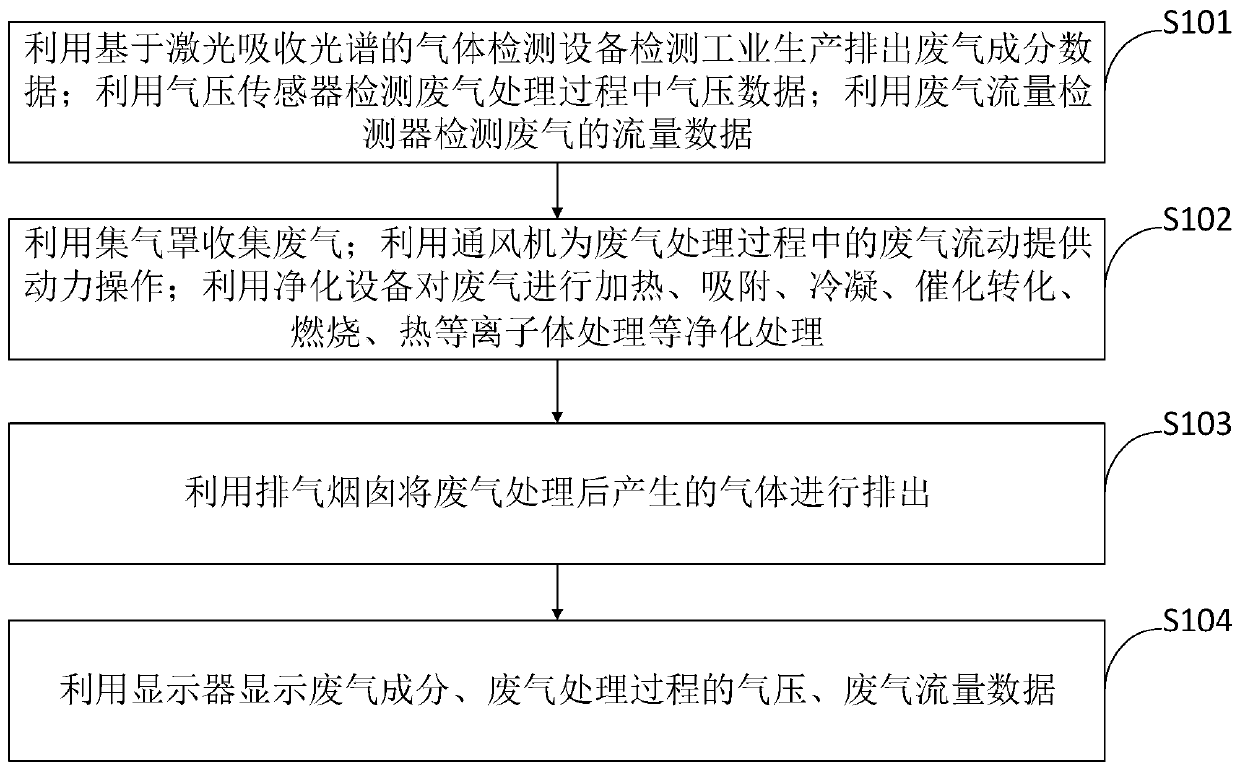
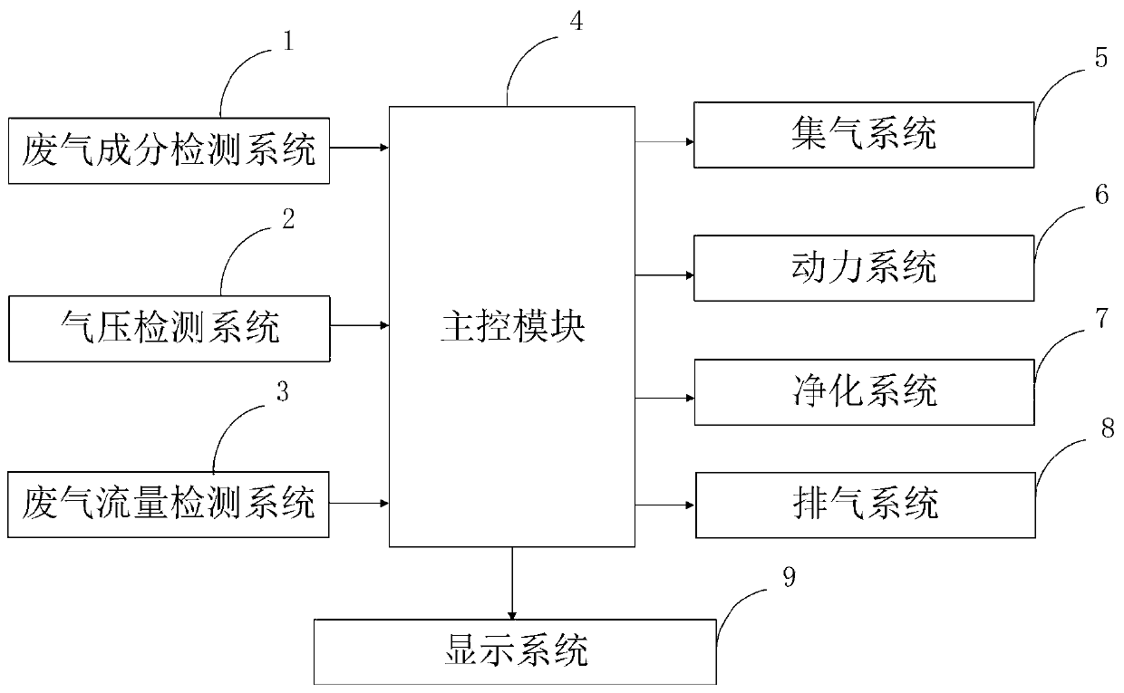
The invention belongs to the technical field of waste gas treatment and discloses harmful waste gas treatment equipment and treatment method. The harmful waste gas treatment equipment comprises a waste gas composition detection system, an air pressure detection system, a waste gas flow detection system, a main control system, a gas collecting system, a power system, a purification system, an exhausting system and a display system. By means of a waste gas flow detection system, great demands of an industrial waste wind power detection system and dynamic detection equipment for control of atmospheric environmental pollution at present are met, and a monitoring means is provided for treatment of atmospheric pollution at present; meanwhile, acidic waste gas and organic waste gas can be removedsimultaneously through the purification system, and the purification effect is good; waste gas is firstly heated before entering a waste gas washing tower, the reaction activity of waste gas molecules is favorably increased, reaction of waste gas and an absorption treatment solution is promoted, absorption of waste gas is more thorough, and the purification effect is improved.

Description

technical field [0001] The invention belongs to the technical field of waste gas treatment, and in particular relates to a treatment equipment and method for harmful waste gas. Background technique [0002] Exhaust gas refers to the poisonous and harmful gas emitted by human beings in the process of production and life. Especially chemical plants, steel plants, pharmaceutical plants, coking plants, oil refineries, etc., and the production of domestic waste gas from human life, the exhaust gas has a strong smell, which seriously pollutes the environment and affects human health. There are many types of pollutants in exhaust gas, their physical and chemical properties are very complex, and their toxicity is also different. The exhaust gas discharged from fuel combustion contains sulfur dioxide, nitrogen oxides (NOx), hydrocarbons, etc.; due to the different raw materials and processes used in industrial production, various harmful gases and solid wastes are emitted, containin...

Claims


Application Information

Patent Timeline
Patent Type & Authority Applications(China)
IPC IPC(8): B01D53/04B01D53/14B01D53/32F23G7/07G01F1/00G01L7/00G01N21/39
CPCB01D53/04B01D53/1456B01D53/32F23G7/07G01F1/00G01L7/00G01N21/39Y02A50/20
Inventor 叶华阳
Owner 驿涛工程集团有限公司
Learn More