
High-performance flyback switching power supply circuit and working method thereof

A switching power supply circuit and flyback technology, applied in electrical components, regulating electrical variables, instruments, etc., can solve the problems of inability to stabilize the output current capability of the latter stage load, imperfect protection measures, and poor transient control characteristics. Achieve the effect that is conducive to high-performance work, improve controllability and reliability, and achieve flow resistance

Pending Publication Date: 2020-06-05
唐山尚新融大电子产品有限公司
View PDF0 Cites 0 Cited by
  • Summary
  • Abstract
  • Description
  • Claims
  • Application Information

AI Technical Summary

Problems solved by technology

Since the flyback switching power supply provides energy output to the load only when the control switch is turned off, the transient control characteristics of the output voltage of the flyback switching power supply are relatively poor, with low performance and poor reliability.
[0003] However, in the current design of the current flyback switching power supply, a single power switch tube is generally used as the chopper switch of the primary coil, and the transient control characteristics are very poor. Due to the use of a dedicated chip for control, relative self-regulation cannot be done. Unable to smoothly output current capacity for the latter stage of load, the protection measures are not perfect, there are almost no redundant measures, and the safety and reliability are very low

Method used


Image

  • High-performance flyback switching power supply circuit and working method thereof
  • High-performance flyback switching power supply circuit and working method thereof

Examples


Embodiment 1

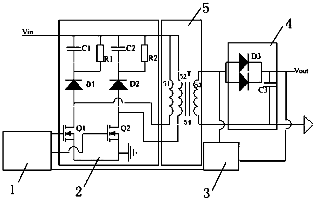
[0036] see figure 1 , in an embodiment of the present invention, a high-performance flyback switching power supply circuit includes a performance control module 1, a power redundancy module 2, a protection module 3 and a transformer 5, the performance control module 1 is connected to the power redundancy module 2, and the power The redundancy module 2 is connected to the transformer module 5, the performance control module 1 is also connected to the protection module 3, and the protection module 3 is connected to the transformer module 5 at the same time;

[0037] The power redundancy module 2 includes a capacitor C1, a capacitor C2, a resistor R1, a resistor R2, a freewheeling diode D1, a freewheeling diode D2, a chopping power MOS transistor Q1 and a chopping power MOS transistor Q2, and the freewheeling diode D1 The cathode of the capacitor C1 is connected to one end of the resistor R1, the capacitor C1 and the resistor R1 are connected in parallel, the anode of the freewhe...

Embodiment 2

[0044] see figure 1 , in an embodiment of the present invention, a high-performance flyback switching power supply circuit includes a performance control module 1, a power redundancy module 2, a protection module 3 and a transformer 5, the performance control module 1 is connected to the power redundancy module 2, and the power The redundancy module 2 is connected to the transformer module 5, the performance control module 1 is also connected to the protection module 3, and the protection module 3 is connected to the transformer module 5 at the same time;

[0045] The power redundancy module 2 includes a capacitor C1, a capacitor C2, a resistor R1, a resistor R2, a freewheeling diode D1, a freewheeling diode D2, a chopping power MOS transistor Q1 and a chopping power MOS transistor Q2, and the freewheeling diode D1 The cathode of the capacitor C1 is connected to one end of the resistor R1, the capacitor C1 and the resistor R1 are connected in parallel, the anode of the freewhe...


PUM


Abstract

The invention relates to the technical field of power circuits, and particularly relates toa high-performance flyback switching power supply circuit which comprises a performance control module, a power redundancy module, a protection module and a transformer. The performance control module is connected with the power redundancy module; the power redundancy module is connected with the transformermodule; the performance control module is further connected with the protection module; and the protection module is connected with the transformer module at the same time. According to the invention, current can be stably output under the condition of sudden load change; power output is smooth; a programmable chip is adopted as a control chip, which facilitates self-adjustment of the power supply; high protection measures are taken; redundant design is added; and safety, reliability and load capacity are improved.

Description

technical field [0001] The technical field of the power supply circuit of the present invention is specifically a high-performance flyback switching power supply circuit and its working method. Background technique [0002] With the development of power electronics technology, power modules have been widely used in various fields, and switching power supplies have gradually replaced linear power supplies and become mainstream power supplies. Under the action of PWM, the power switch tube of the switching power supply performs the opening and closing actions, and chops the bus voltage into a pulse voltage. The drive control circuit controls the duty cycle of the PWM to ensure the stability of the voltage. In small and medium power DC-DC switching power supplies, the most commonly used circuit topology is flyback switching power supply and forward circuit. Since the flyback switching power supply provides energy output to the load only when the control switch is turned off, ...

Claims


Application Information

Patent Timeline
IPC IPC(8): H02M3/335H02M1/32
CPCH02M1/32H02M3/33569H02M1/325
Inventor 李建江
Owner 唐山尚新融大电子产品有限公司
Learn More