Driving device for new energy motor vehicles

A technology for driving devices and motor vehicles, which is applied to the arrangement of multiple prime movers of power devices, pneumatic power devices, and general power devices, and can solve unfavorable motor vehicle weight control and space layout, ride experience and cruising range Unable to meet the problems, such as large volume of the mechanism, to achieve the effect of easy installation and arrangement, compact structure and reduced volume

Inactive Publication Date: 2018-05-08
湖州伊立机械有限公司
View PDF7 Cites 0 Cited by
  • Summary
  • Abstract
  • Description
  • Claims
  • Application Information

AI Technical Summary

Problems solved by technology

[0002] Existing new energy motor vehicles still have the problems of poor driving feeling and high energy consumption when the driving state changes greatly and quickly, such as starting and re-accelerating, resulting in their ride experience and cruising range unable to meet people's normal needs. At the same time, the power device used in the driving device of a general new energy motor vehicle switches between different speed ratios through more shafts and gears. The mechanism is large in size and heavy in weight, which is not conducive to the weight control and space layout of the motor vehicle.

Method used


Image

  • Driving device for new energy motor vehicles

Examples


Embodiment 1

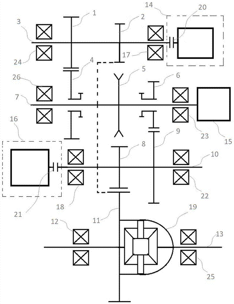
[0040] Such as figure 1 A driving device for a new energy motor vehicle shown includes a rotating mechanism arranged between the driver and the output device, wherein the transmission mechanism includes an input shaft 7 and a first transmission shaft with planets arranged on the circumference of the input shaft 7 3. The second transmission shaft 10; wherein, the driver includes a power source 15, the power source 15 is a motor or an internal combustion engine, the power source 15 is coupled to the input shaft 7, and the first input bearing 26 and the second input shaft 7 are respectively arranged at both ends of the input shaft 7. Bearing 23; wherein, the first drive gear 4 and the second drive gear 6 are empty between the first and second input bearings 26, 23 of the input shaft 7; wherein, the first and second drive gears 4, 6 of the input shaft 7 6 is provided with a synchronizing device 5 in the middle; wherein, the first transmission bearing 24 and the second transmission...

Embodiment 2

[0050] The technical solution described in embodiment two is similar to embodiment one, and its difference is:

[0051]In this embodiment, the driver further includes a first driving device 14 , the end of the first transmission shaft 3 provided with a first transmission bearing 24 is connected to the first driving device 14 through a first clutch device 20 , and the first driving device 14 is a motor.

[0052] The second transmission shaft 10 does not have a driver at both ends.

Embodiment 3

[0054] The technical solution described in embodiment three is similar to embodiment one, and its difference is:

[0055] In this embodiment, the driver further includes a second driving device 16, the end of the second transmission shaft 10 provided with the third transmission bearing 18 is connected to the second driving device 16 through the second clutch device 21, and the second driving device 16 is a motor.

[0056] There is no driver at both ends of the first transmission shaft 3 .


PUM


Abstract

A driving device for new energy motor vehicles includes a transmission mechanism disposed between an actuator and an output device. The actuator includes a power source, the power source is connectedwith an input shaft in a coupling mode. The transmission mechanism includes the input shaft, and a first transmission shaft and a second transmission shaft both arranged in the circumferential direction of the input shaft in a planet mode. The output device includes a main deceleration output gear and a differential mechanism coupled to each other. Through the different speed ratios formed by twodifferent tooth ratios including the tooth ratio of a first driving gear and a first transmission gear and the tooth ratio of a second driving gear and a second transmission gear, the switching of transmission states can be achieved. The actuator also includes a first driving device and a second driving device both connected with the first and second transmission shafts to assist in regulating thestability of power transmission and optimize energy consumption. The driving device for new energy motor vehicles has the advantages of high energy utilization efficiency, large energy density, low energy consumption, compact structure, stable power output, flexible switching, high overall structural strength, and long service life.

Description

technical field [0001] The invention relates to a power transmission device of a motor vehicle, in particular to a driving device for a new energy motor vehicle. Background technique [0002] Existing new energy motor vehicles still have the problems of poor driving feeling and high energy consumption when the driving state changes greatly and quickly, such as starting and re-accelerating, resulting in their ride experience and cruising range unable to meet people's normal needs. At the same time, the power device used in the driving device of general new energy motor vehicles switches between different speed ratios through more shafts and gears. The mechanism is large in size and heavy in weight, which is not conducive to the weight control and space layout of the motor vehicle. Contents of the invention [0003] The purpose of the present invention is to provide a drive device for new energy vehicles with high energy utilization efficiency, high energy density, low energ...

Claims


Application Information

Patent Timeline
IPC IPC(8): B60K6/36B60K6/40B60K17/04B60K17/16
CPCY02T10/92B60K6/36B60K6/40B60K17/04B60K17/16
Inventor 朱正林
Owner 湖州伊立机械有限公司
Why Eureka
Try Eureka