
Radial force accurate compensation decoupling control method for bearingless permanent magnet synchronous motor

A permanent magnet synchronous motor, decoupling control technology, applied in the direction of motor generator control, AC motor control, electronic commutation motor control, etc., can solve problems such as nonlinear coupling, avoid coordinate transformation, improve control accuracy and dynamic Response speed and the effect of reducing the amount of computation

Active Publication Date: 2020-06-05
ZHEJIANG UNIV +1
View PDF11 Cites 5 Cited by
  • Summary
  • Abstract
  • Description
  • Claims
  • Application Information

AI Technical Summary

Problems solved by technology

[0004] The main purpose of the present invention is to provide a bearingless permanent magnet synchronous motor radial force accurate compensation decoupling control method to solve the problem of non-linear coupling between displacements in the α and β directions existing in the bearingless permanent magnet synchronous motor, and to improve Performances such as control accuracy and dynamic response speed of bearingless permanent magnet synchronous motor rotor suspension

Method used


Image

  • Radial force accurate compensation decoupling control method for bearingless permanent magnet synchronous motor
  • Radial force accurate compensation decoupling control method for bearingless permanent magnet synchronous motor
  • Radial force accurate compensation decoupling control method for bearingless permanent magnet synchronous motor

Examples


Embodiment Construction

[0029] In order to make the content of the present invention more obvious and understandable, the present invention will be described in detail below in conjunction with specific examples.

[0030] Core idea of ​​the present invention:

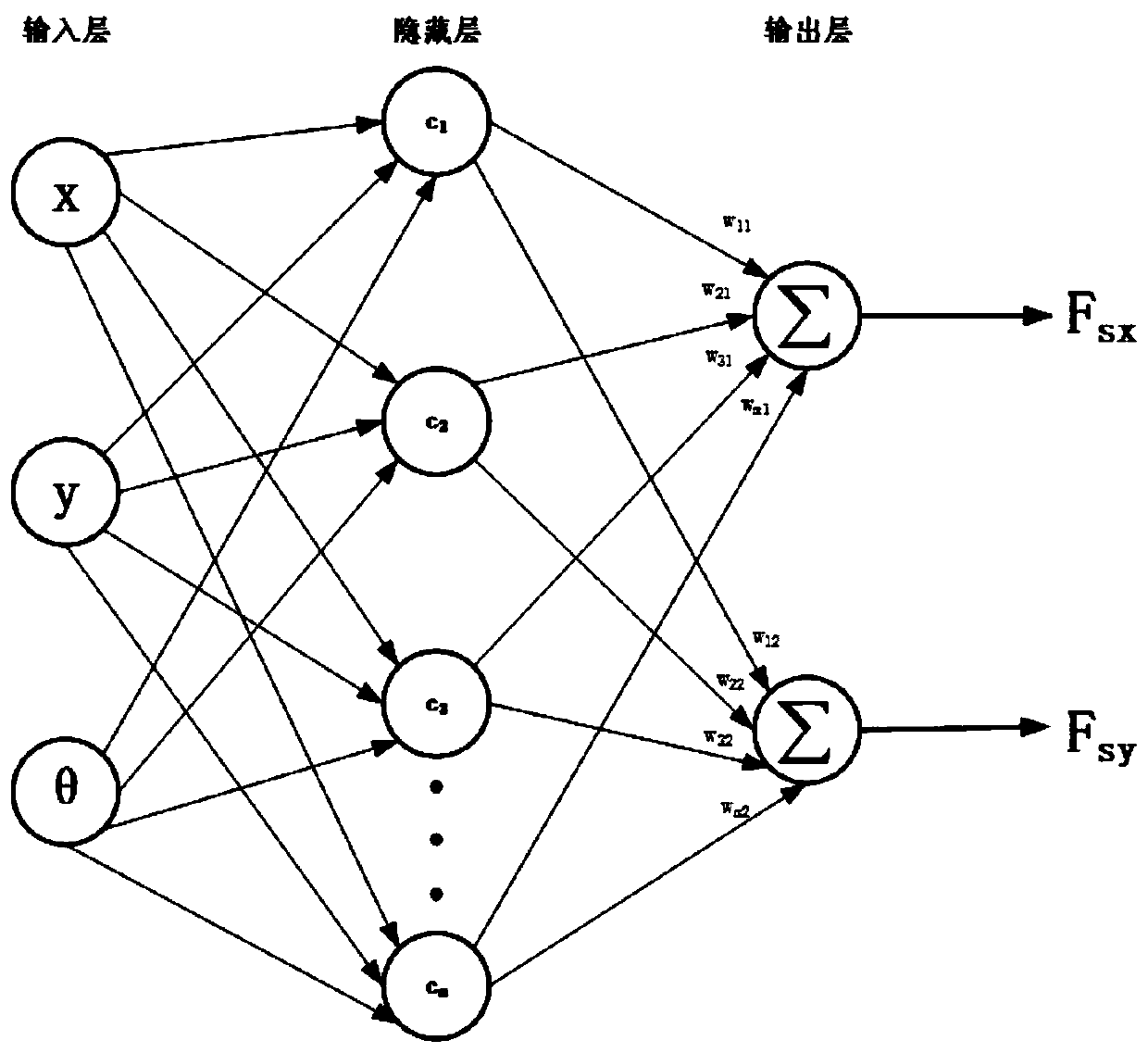
[0031] (1) There is a strong nonlinear coupling between the displacement of the rotor of the bearingless permanent magnet synchronous motor in the α and β directions. If the compensation and decoupling of the eccentric force are not used in the control, the overall dynamic and static control of the system will be reduced. performance. The traditional linear eccentric force compensation method ignores the nonlinearity of coupling between x and y displacements and the change of motor system parameters, so the improvement of the control performance of the suspension subsystem is limited.

[0032] (2) The RBF neural network can approximate any continuous system with arbitrary precision. The RBF neural network system obtained through offline train...


PUM


Abstract

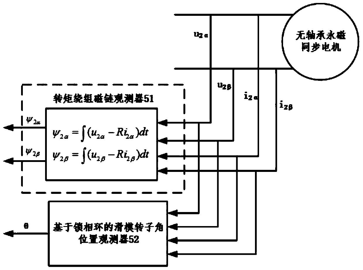
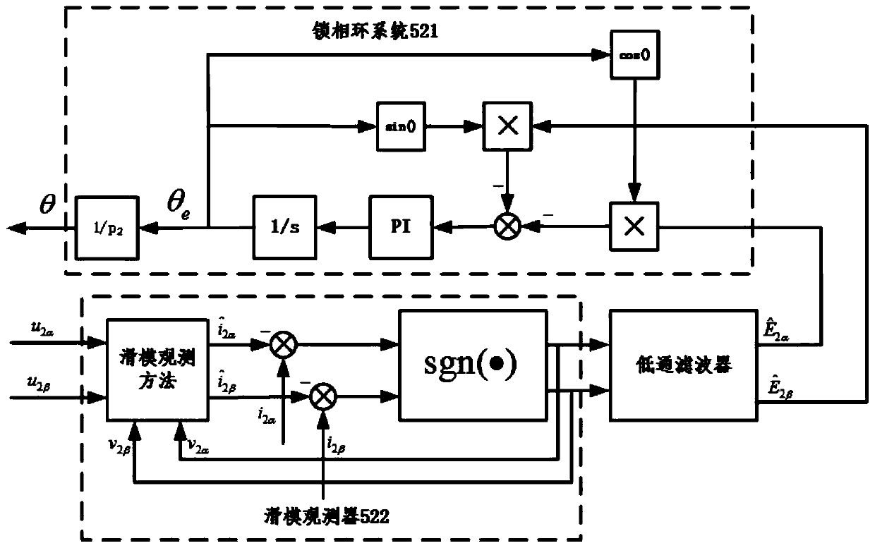
The invention provides a radial force accurate compensation decoupling control method for a bearingless permanent magnet synchronous motor. According to the method, a position controller, a force / current converter, a current controller, a radial displacement sensing module, a torque winding flux linkage and rotor angular position observer, a neural network and a voltage type inverter are included,and the method comprises the steps of offline training the neural network to determine a force-position model of the bearingless permanent magnet synchronous motor system; feeding a radial displacement sensing measurement signal and a rotor angular position observation signal back to the input end of the neural network, superposing an obtained output signal with an output signal of the position controller, thereby achieving the precise compensation decoupling control of the radial force of the bearingless permanent magnet synchronous motor. According to the method, the nonlinear coupling problem between the radial positions x and y of a rotor is solved, the dynamic and static system performance, such as the control precision and the response speed of rotor suspension, etc., is improved,and the purpose of high-precision control over the suspension subsystem of the bearingless permanent magnet synchronous motor is achieved.

Description

technical field [0001] The invention relates to the technical field of motor control, in particular to a precise compensation and decoupling control method for radial force of a bearingless permanent magnet synchronous motor, which is suitable for high-performance control of a bearingless permanent magnet synchronous motor. Background technique [0002] The bearingless motor suspends the rotor in the inner space of the motor through the force of the magnetic field, eliminating the mechanical bearing that supports the motor rotor in the traditional motor. Bearingless motors combine the functions of magnetic suspension bearings and motors, and have the advantages of no friction, no wear, no pollution, no lubrication, maintenance-free operation, high durability, high speed and high precision, and reduce system complexity compared with magnetic suspension bearings and the axial length of the rotor; bearingless motors have broad application prospects in the fields of machine tool...

Claims


Application Information

Patent Timeline
Patent Type & Authority Applications(China)
IPC IPC(8): H02P21/00H02P21/13H02P6/182H02P25/022
CPCH02P6/182H02P21/0007H02P21/0014H02P21/13H02P25/022
Inventor 付新李玲玲苏芮胡亮
Owner ZHEJIANG UNIV
Learn More