Paint spraying equipment

A technology of spray painting equipment and support frame, which is applied in painting room, metal processing equipment, grinding/polishing equipment, etc., can solve the problems of heavy wood strips, labor consumption, and easy generation of wood chips, so as to save drying space and shorten the time. The effect of resting time and reducing the occupied space

Active Publication Date: 2020-06-09
TAICANG CITY LVDIAN INFORMATION TECH CO LTD
View PDF7 Cites 10 Cited by
  • Summary
  • Abstract
  • Description
  • Claims
  • Application Information

AI Technical Summary

Problems solved by technology

Furthermore, the surface painting treatment of many existing metal pipes and plastic pipes also adopts the traditional artificial painting method.
For some small workshops, traditional manual painting is used. When painting, first support the two ends of the wooden strips, and then paint the upper end and both sides of the wooden strips. After brushing, it needs to stand for about 2 hours. , and then reverse the wooden strip and paint the bottom end of the wooden strip. During the whole painting process, there are the following problems: 1. When the wooden strip is standing still, the paint on the side flows downward due to the influence of gravity, and many All flow to the bottom of the wooden strips and accumulate in an irregular shape, which greatly affects the appearance
2. The wooden strip is relatively heavy, so it is difficult to turn over and apply paint, and it is easy to get the paint on your hands
3. In order to be beautiful and convenient for painting, the wooden strips need to be polished before painting, which consumes a lot of labor and energy. At the same time, it is easy to produce sawdust during polishing, which is easy to fly into the eyes and respiratory tract
4. The paint contains a large amount of harmful substances such as formaldehyde, especially in the process of painting, the smell is particularly strong, causing great harm to the human body

Method used


Image

  • Paint spraying equipment
  • Paint spraying equipment
  • Paint spraying equipment

Examples


Embodiment Construction

[0037] In order to better understand the present invention, the implementation manner of the present invention will be explained in detail below in conjunction with the accompanying drawings.

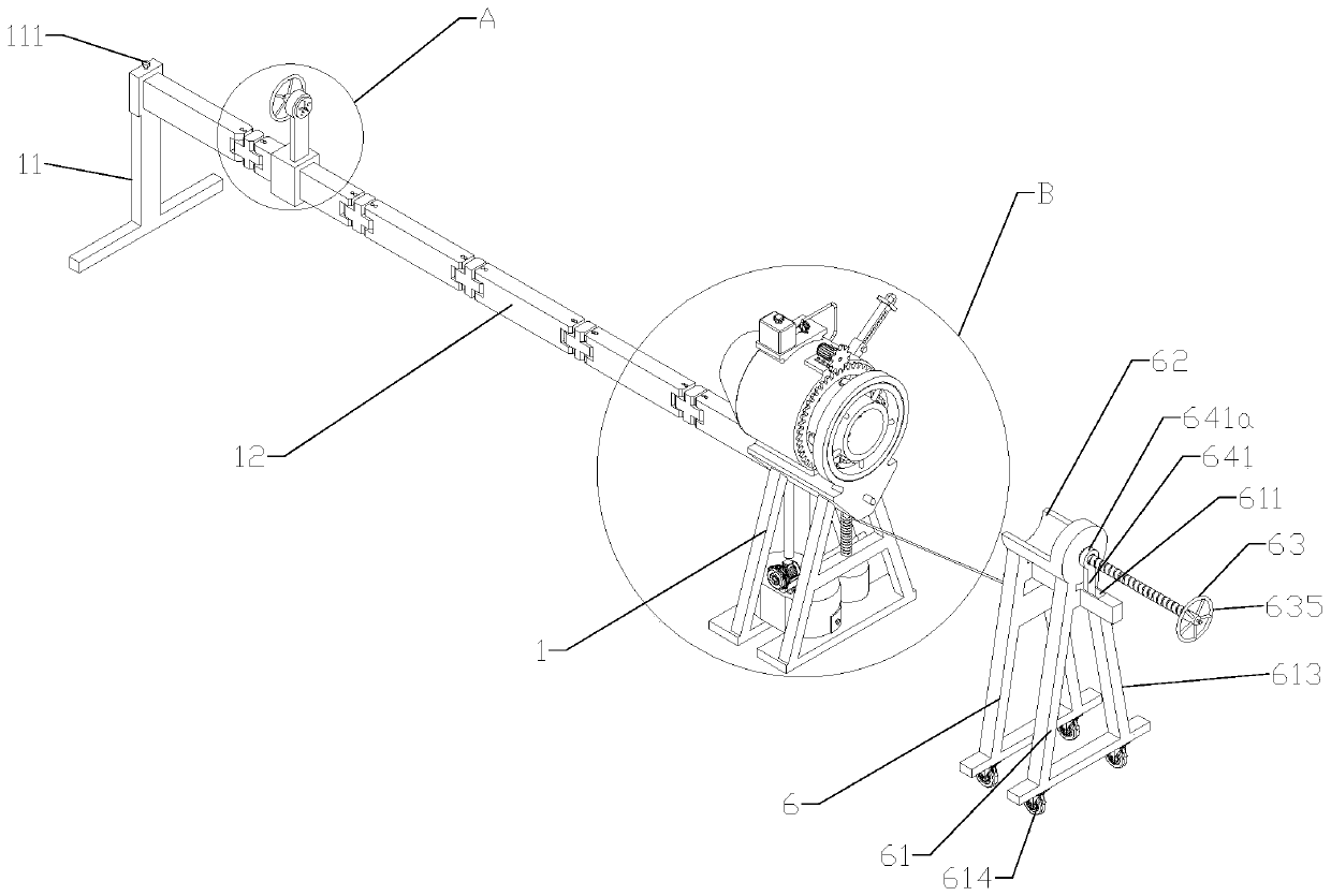
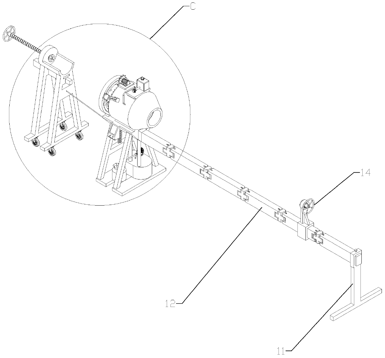
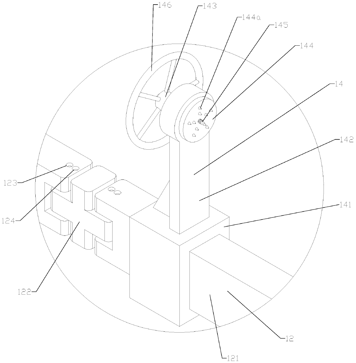
[0038] as attached figure 1 to attach Figure 15 Shown painting equipment, it comprises first supporting frame 1 and second supporting frame 6, and first supporting frame 1 comprises front supporting leg 11, folding rod 12 and rear supporting leg 13 successively from front to rear, the upper end of front supporting leg 11 Sleeved on the folding rod 12, the upper end of the front leg 11 is threaded with a bolt 111, and the bolt 111 moves downward to tighten the folding rod 12. During use, the front leg 11 is fixed by screwing the bolt 111. The folding rod 12 includes a connecting rod 121 and a cross-shaped connecting head 122. The connecting rod 121 and the cross-shaped connecting head 122 are respectively provided with a hinged connection hole 123 and a limiting hole 124. Remove pins....


PUM


Abstract

The invention discloses paint spraying equipment. The paint spraying equipment comprises a first supporting frame and a second supporting frame, wherein the first supporting frame sequentially comprises a front supporting leg, a folding rod and a rear supporting leg from front to back; a batten front end clamping device is slidably arranged on the folding rod; and the upper end of the rear supporting leg is connected with a fixing seat, a barrel with opens at front and rear is fixed to the fixing seat, and a clamping mechanism, a grinding device, a paint spraying device and a drying device aresequentially arranged in the barrel from back to front. The paint spraying equipment has the characteristics of preventing paint from accumulating to the bottom end, automatically grinding and preventing pollution.

Description

technical field [0001] The invention relates to a paint spraying equipment for long objects such as wooden strips, metal pipes and plastic pipes. Background technique [0002] For decoration or outdoor use of round or square wooden strips, the surface generally needs to be painted or brushed with tung oil to make it beautiful and anti-corrosion. Some wooden strips are longer, such as outdoor gazebos or other timber constructions, which can be up to three or four meters long. Furthermore, the surface painting treatment of many existing metal pipes and plastic pipes also adopts the traditional manual painting treatment method. For some small workshops, traditional manual painting is used. When painting, first support the two ends of the wooden strips, and then paint the upper end and both sides of the wooden strips. After brushing, it needs to stand for about 2 hours. , and then reverse the wooden strip and paint the bottom end of the wooden strip. During the whole painting ...

Claims


Application Information

Patent Timeline
Patent Type & Authority Applications(China)
IPC IPC(8): B05B16/20B05B13/02B05B9/04B05B14/40B24B21/00B24B47/22B24B55/06B24B55/12B24B21/20B24B55/04
CPCB05B9/0403B05B13/0207B24B21/00B24B21/20B24B47/22B24B55/04B24B55/06B24B55/12B05B14/40B05B16/20
Inventor 刘文龙
Owner TAICANG CITY LVDIAN INFORMATION TECH CO LTD
Why Eureka
Try Eureka