Aircraft carrier plane rotary catapult-assisted take-off platform

A carrier-based aircraft and aircraft carrier technology, applied in the field of military weapons, can solve the problems of aircraft weight restrictions, vulnerability to attack, and large volume and weight, and achieve low weight cost and energy consumption, strong speed controllability, and simple technical structure Effect

Active Publication Date: 2020-06-09
杨剑
View PDF8 Cites 1 Cited by
  • Summary
  • Abstract
  • Description
  • Claims
  • Application Information

AI Technical Summary

Problems solved by technology

[0004] Ski jump take-off means that the aircraft relies on its own thrust to run and accelerate on a straight deck, and then flies upwards in a high parabolic state through the upturned ski jump deck. After leaving the aircraft carrier deck, it continues to rely on the power of the carrier aircraft engine Thrust and inertia continue to fly upwards, but the ski jump takeoff has the following disadvantages: 1. When the carrier-based aircraft takes off, the aircraft carrier is required to sail at full speed against the wind, which is vulnerable to attack during wartime; 2. The carrier-based aircraft required to take off has a large thrust-to-weight ratio, and the It will consume a large amount of airborne fuel and reduce its combat radius; 3. There are restrictions on the weight of the aircraft that take off, which affects the fuel capacity and ammunition capacity of the carrier-based aircraft, and cannot take off heavy aircraft such as fixed-wing early warning aircraft. ;4. Ski jump take-off requires a runway run-up, which takes up a lot of deck area and affects the number and diversification of aircraft carriers.
[0005] Steam catapult take-off is to use the energy of the aircraft carrier itself to generate high-pressure steam to push the piston, and then drive the carrier-based aircraft to accelerate to the take-off speed of the carrier-based aircraft in a very short time distance to assist take-off, but steam catapult take-off has the following disadvantages: 1 1. Huge volume and weight; 2. Complicated layout structure; 3. Large amount of maintenance and long maintenance period; 4. It will consume a lot of fresh water; 5. The problem of U-shaped cylinder seal leakage is complicated; The airframe structure and the pilot have a great influence; 7. Poor controllability and low energy utilization
[0006] Electromagnetic catapult take-off is based on the principle of linear motors, and uses the strong repulsion between electromagnetics to push the carrier-based aircraft to accelerate to the take-off speed in a short distance and in a short time, and then eject the carrier-based aircraft into the air to take off. Compared with steam catapult, electromagnetic catapult Great progress has been made in terms of volume weight, failure rate, controllability, energy utilization rate and smooth thrust output curve, but there are still the following disadvantages: 1. High technical threshold and expensive price; 2. Requires a large amount of electric energy and supporting equipment The power generation system of the aircraft carrier has high requirements on the power energy of the aircraft carrier and takes up a lot of space; 3. The strong magnetic field during take-off will cause electromagnetic interference to the work of airborne electronic equipment and airborne weapons

Method used


Image

  • Aircraft carrier plane rotary catapult-assisted take-off platform
  • Aircraft carrier plane rotary catapult-assisted take-off platform

Examples


Embodiment 1

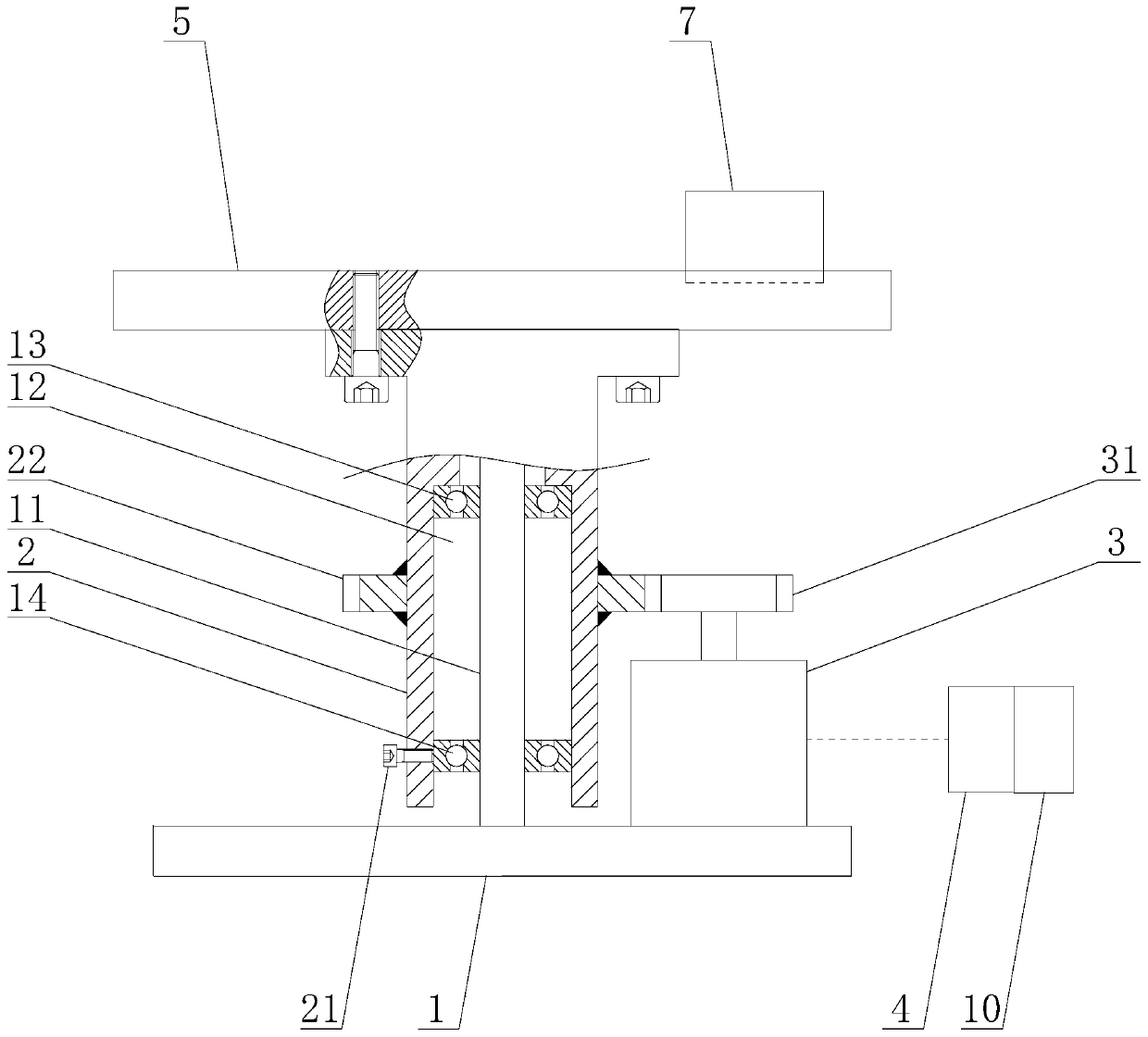
[0023] Embodiment 1: as attached figure 1 , attached figure 2As shown, the present invention shows that the aircraft carrier-borne aircraft rotary ejection take-off platform includes a rotating seat support 1, and the top of the rotating seat support 1 is vertically provided with a rotating column 2, and the rotating column 2 and the rotating seat support The seat 1 is connected in rotation. Preferably, in order to ensure the stability of the rotation of the rotating column 2, the top of the rotating seat support 1 is vertically welded with a support shaft 11, and the middle part of the bottom of the rotating column 2 is provided with a support shaft 11. Compatible mounting hole 12, support shaft 11 is inserted in the mounting hole 12, upper bearing 13 is installed on the top of described support shaft 11, lower bearing 14 is installed on the bottom of described support shaft 11, upper bearing 13, lower bearing 14 The outer rings are in contact with the inner wall of the mou...

Embodiment 2

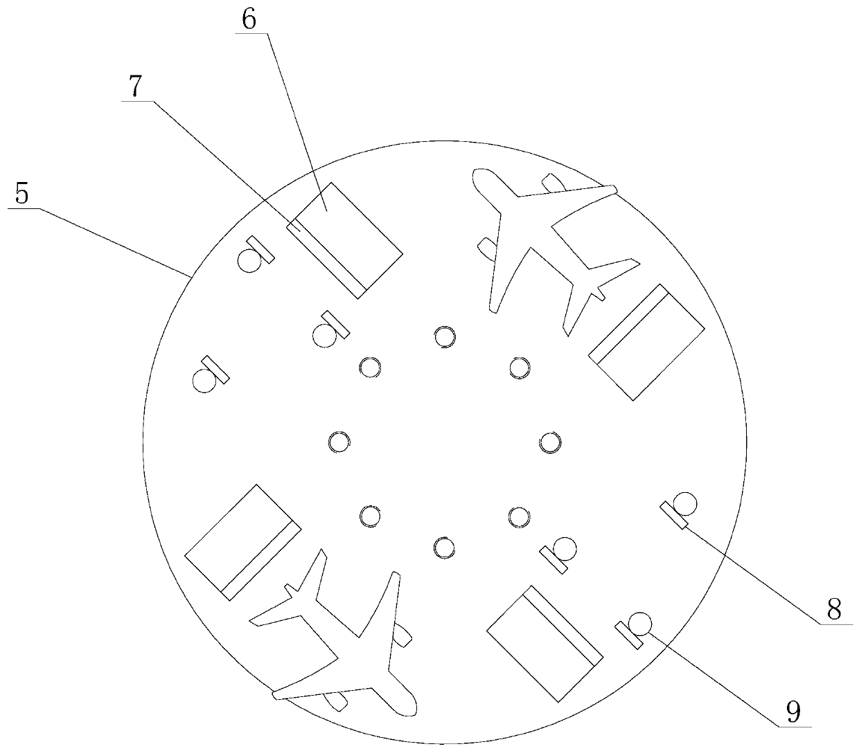
[0026] Embodiment 2: On the basis of Embodiment 1, in order to increase the quantity of ejecting carrier-borne aircraft, the quantity of said rotating platform 5 is at least one, and is fixed on the rotating column 2 successively from bottom to top, for example, can be set as Three rotating platforms 5, wherein the uppermost rotating platform 5 is fixed on the top of the rotating column 2, adopts a multi-layer design to increase the number of carrier-based aircraft ejected at a single time.


PUM


Abstract

The invention discloses an aircraft carrier plane rotary catapult-assisted take-off platform, and mainly relates to the field of military weapons. The take-off platform includes a rotary seat support,a rotary column is vertically arranged at the top of the rotary seat support, a rotary table is arranged on the rotary column, a plurality of gate positions are arranged on the top of the rotary table in an annular array mode, a baffle plate groove is formed in one end of each gate position, a baffle plate capable of being opened and closed is arranged in each baffle plate groove, and a locking device used for locking wheels of a plane is arranged on one side of each baffle plate groove. The beneficial effects of the invention are that: the technical structure is simple, the weight cost and the energy consumption are relatively low, few parts are involved, and the maintenance need is few, a plurality of planes can be catapulted to take off simultaneously or continuously, take off is carried out in a gentle and uniform acceleration rotating mode, fresh water is not needed, the wind direction is not considered, the instantaneous load is smooth, the range of planes suitable for take-offis wide, the speed controllability is high, runway run-up is not needed, excessive deck area is not occupied, no electromagnetic interference exists, and rising or multi-layer design can be achieved.

Description

technical field [0001] The invention relates to the field of military weapons, in particular to a rotary catapult take-off platform for aircraft carrier-borne aircraft. Background technique [0002] An aircraft carrier is the product of the combination of aircraft and warships. It is a large surface ship with carrier-based aircraft as its main combat weapon. The aircraft carrier itself is a mobile airport, which exists to allow aircraft to take off and land, maintain them and enable them to operate for a long time. The carrier-based aircraft can rely on the endurance of the aircraft carrier, can provide air support far away from the country's mainland, and has long-range strike capabilities. It is one of the most important combat ships to seize air supremacy and sea supremacy. Among them, the number of aircraft carried by aircraft carriers and the take-off and landing efficiency are important indicators to measure the combat effectiveness of aircraft carriers. As the aircr...

Claims


Application Information

Patent Timeline
IPC IPC(8): B64F1/06
CPCB64F1/06
Inventor 杨剑
Owner 杨剑
Why Eureka
Try Eureka