A buried structure and method for preventing cracking of luminous signs on concrete pavement

A technology for concrete pavement and luminous signs, which is applied to road signs, road lights, and pavements paved with prefabricated blocks, etc., to achieve cost reduction, simple construction methods, and uneven improvement

Active Publication Date: 2021-08-03
NANTONG TIANCHENG OPTOELECTRONICS TECH CO LTD
View PDF0 Cites 0 Cited by
  • Summary
  • Abstract
  • Description
  • Claims
  • Application Information

AI Technical Summary

Problems solved by technology

[0004] The object of the present invention is to provide a buried structure and method for preventing cracking at the luminous sign on the concrete pavement, which can effectively alleviate the problems of cracking, potholes, aggregate loosening and falling off caused by the reflective cracks on the concrete pavement at the luminous sign at the urban intersection. Solve the problems raised in the above-mentioned background technology

Method used


Image

  • A buried structure and method for preventing cracking of luminous signs on concrete pavement
  • A buried structure and method for preventing cracking of luminous signs on concrete pavement
  • A buried structure and method for preventing cracking of luminous signs on concrete pavement

Examples


Embodiment Construction

[0048] The following will clearly and completely describe the technical solutions in the embodiments of the present invention with reference to the accompanying drawings in the embodiments of the present invention. Obviously, the described embodiments are only some, not all, embodiments of the present invention. Based on the embodiments of the present invention, all other embodiments obtained by persons of ordinary skill in the art without making creative efforts belong to the protection scope of the present invention.

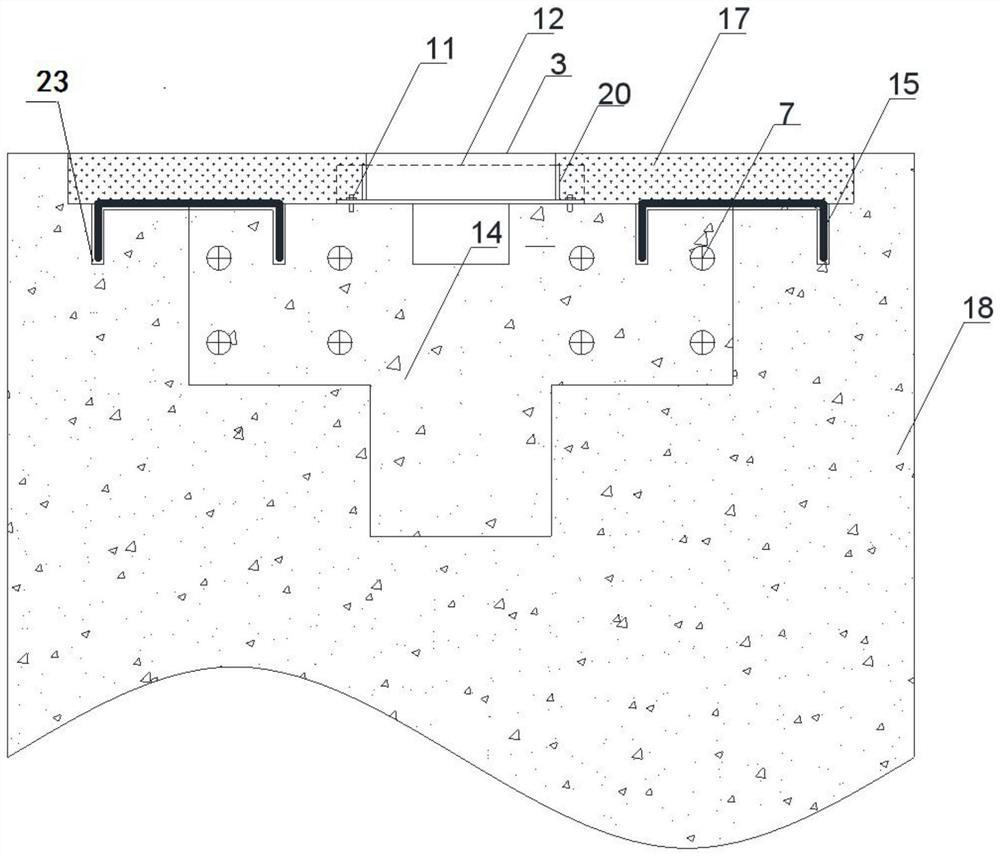
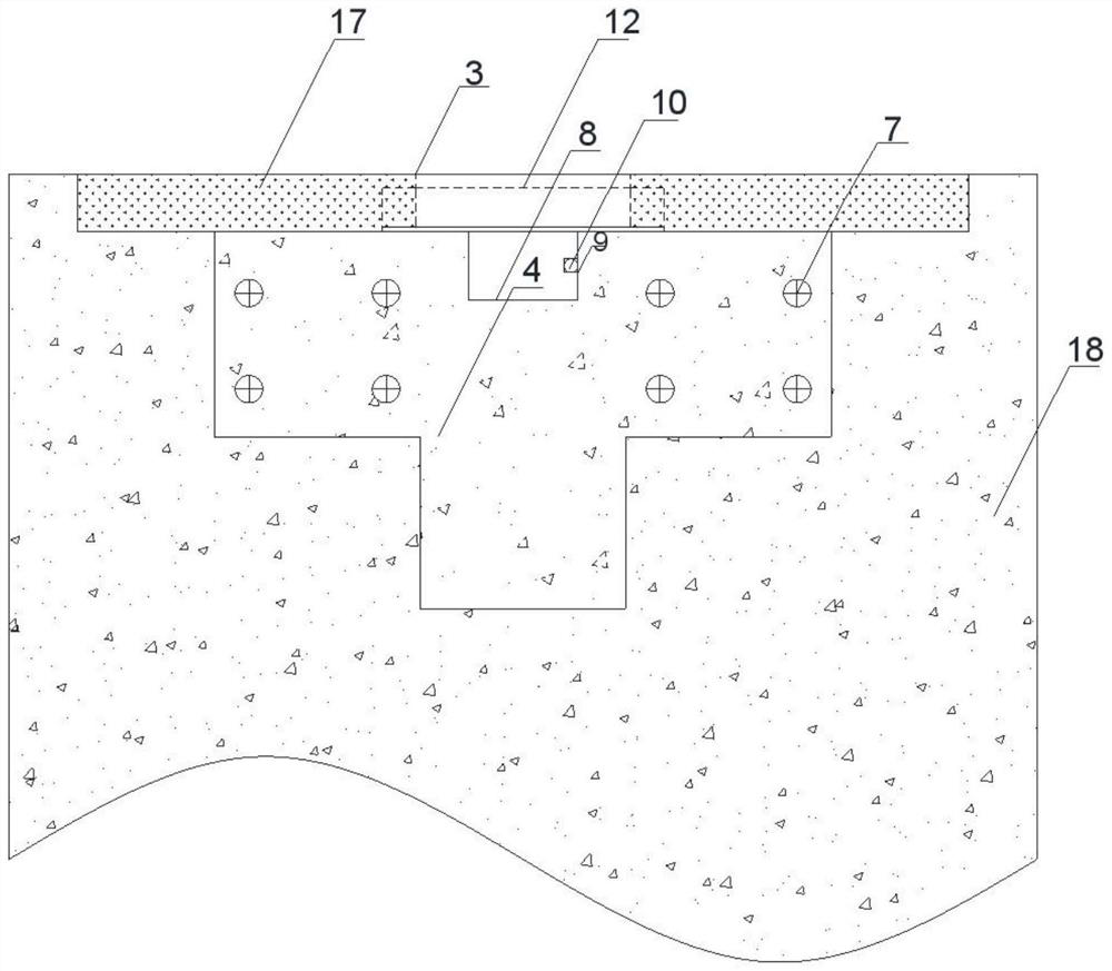
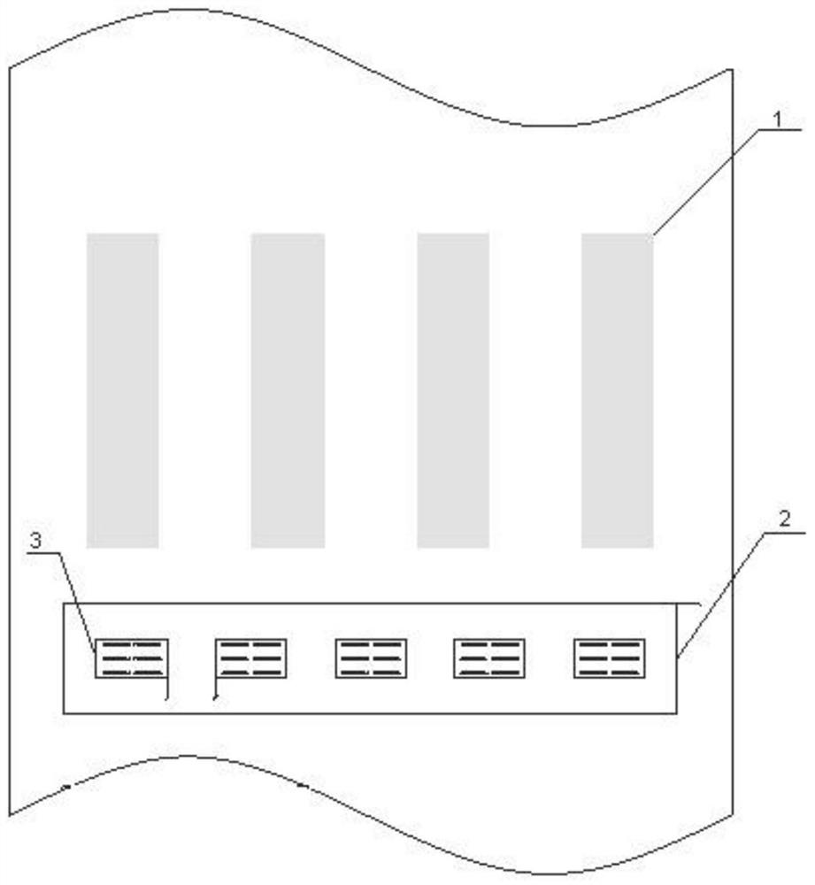
[0049] see Figure 1 to Figure 12 , the present invention provides a technical solution: an embedded structure for preventing cracking of luminous signs on concrete pavement, including pedestrian zebra crossing 1, stepped groove 2, luminous sign 3, shaped plate type member 4, hole 5, PVC casing 6, Steel bar 7, drainage groove 8, buckle 9, plastic pipe 10, first bolt 11, first equilateral angle steel 12, steel plate 13, prefabricated concrete member 14, horsesh...


PUM


Abstract

The invention discloses an embedding structure and method for preventing cracking of luminous signs on concrete pavement. Step-shaped grooves are embedded in the road surface, luminous signs are evenly arranged on the upper surface of prefabricated concrete components, and PVC is arranged in holes on one side of the shaped plate type components. Sleeve, with steel bars in the hole on the other side, drainage grooves in the middle of the upper surface of prefabricated concrete members, strip grooves at equal intervals above the joints, drill holes at both ends of the strip grooves, and horseshoe tendons The middle part fits the strip groove, the two ends of the horseshoe bars are set in the drilled holes, the second equilateral angle steel is set on the upper surface of the prefabricated concrete member, the second equilateral angle steel is symmetrically distributed along the drainage groove, the first equilateral angle steel It is vertically arranged on both sides of the second equilateral angle steel, the luminous sign is arranged between the first equilateral angle steel and the second equilateral angle steel, and the asphalt layer is arranged above the road surface. The invention can improve the anti-reflection crack performance of the concrete surface where the luminous signs are buried, and reduce the width and expansion of the cracks on the concrete pavement.

Description

technical field [0001] The invention relates to the technical field of traffic facilities, in particular to an embedding structure and method for preventing cracks at luminous signs on concrete pavement. Background technique [0002] Compared with asphalt concrete pavement, cement concrete pavement has excellent deformation resistance and water stability. At the end of the last century, cities built a large number of cement concrete pavements. Embedding luminescent signs at the zebra crossings at urban road intersections can effectively warn "head-down people" and reduce the traffic accident rate at intersections. The pavement embedding method of existing pavement signs is to excavate a groove of a certain size in the existing pavement, and then position the cast iron box at the bottom of the light-emitting device on a straight line through the two parallel channel steels at the bottom, and then start pouring concrete in layers It is compacted and formed, maintained, and fi...

Claims


Application Information

Patent Timeline
Patent Type & Authority Patents(China)
IPC IPC(8): E01C17/00E01C5/00E01C11/22E01C23/04E01F9/582
CPCE01C5/003E01C11/225E01C17/00E01C23/04E01F9/582
Inventor 徐勋倩施卫东杨霄徐海黎沈标王建波项宏亮周井玲顾钰雯付尚静
Owner NANTONG TIANCHENG OPTOELECTRONICS TECH CO LTD
Why Eureka
Try Eureka