Hedging energy dissipation type debris flow diversion system

A shunt system and mud-rock flow technology, applied in water conservancy projects, artificial waterways, buildings, etc., can solve the problems of unsatisfactory prevention and control of mud-rock flow, and achieve the effect of strong anti-geological disaster ability, reduced impact force and destructive effect

Active Publication Date: 2020-06-09
NORTH CHINA UNIV OF WATER RESOURCES & ELECTRIC POWER +1
View PDF8 Cites 2 Cited by
  • Summary
  • Abstract
  • Description
  • Claims
  • Application Information

AI Technical Summary

Problems solved by technology

[0006] In order to solve the problem of unsatisfactory prevention and control of debris flow in the existing way of setting up interception dams, the present invention provides a hedge energy dissipation debris flow diversion system, the core of which is a diversion dam and a hedge guide device that cooperate with each other, and the diversion dam is used to guide t

Method used


Image

  • Hedging energy dissipation type debris flow diversion system
  • Hedging energy dissipation type debris flow diversion system
  • Hedging energy dissipation type debris flow diversion system

Examples


Embodiment 1

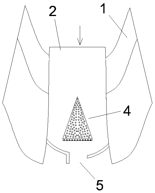
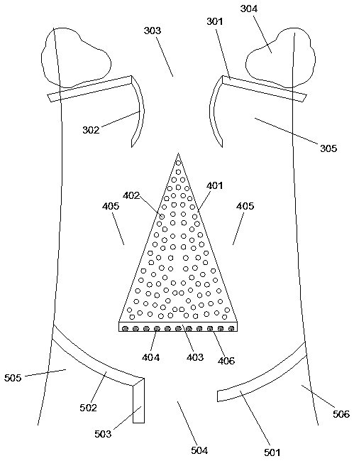
[0036] Such as figure 1 with 3 As shown, an opposing energy dissipation type debris flow diversion system is arranged in the debris flow channel 2 formed between the highlands 1 on both sides. The diversion system includes a diversion dam 4 and an opposite guide device 5, wherein the The diversion dam 4 includes a half-conical first dam body 401 arranged in the middle of the debris flow channel 2, and the tip of the semi-conical shape faces the direction of the debris flow, thereby forming two first diversion channels 405 on both sides thereof;

[0037] The opposing guide device 5 includes a first arc-shaped guide dam 501 and a second arc-shaped guide dam 502 which are respectively arranged in front of the flow direction of the two first branch channels 405, wherein the first arc-shaped guide dam 501 and the second arc The guide dams 502 are arranged obliquely on both sides of the debris flow channel 2, and the first arc-shaped guide dam 501 and the second arc-shaped guide dam 502...

Embodiment 2

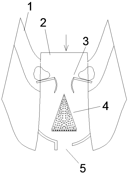
[0045] This embodiment is an improvement scheme made on the basis of embodiment 1. Its basic structure is the same as that of embodiment 1. The improvement is as follows: Image 6 As shown, the two sides of the middle of the first dam body 401 are symmetrically provided with an impact redirecting plate 407. The free end of the impact redirecting plate 407 is inclined to extend in the upstream direction, and its free end is connected to the side of the debris flow channel 2. There is a gap, so that the debris flow of the first branch channel 405 impacts on the impact direction changing plate 407 and then changes direction again and slows down, thereby enclosing a stagnation zone between its front surface and the side wall of the first dam 401, The back water surface and the side wall of the first dam body 401 enclose a stagnant area.

Embodiment 3

[0047] This embodiment is an improvement scheme made on the basis of embodiment 2. Its basic structure is the same as that of embodiment 2. The improvement is as follows: Figure 7 As shown, the two sides of the rear part of the first dam body 401 are symmetrically provided with secondary diverging plates 408, the secondary diverging plates 408 are V-shaped distributed along the direction of the debris flow, and the upstream end of the secondary diverging plate 408 is connected to the impact direction changing plate 407. There is a gap between the free ends to form an overflow channel, and another overflow channel is formed between the upstream end and the side of the debris flow channel 2; the V-shaped tip of the secondary splitter plate 408 is located on the side of the debris flow channel 2, thereby A debris flow deceleration zone 409 is formed between the secondary diversion plate 408 and the high ground 1 on the side.

[0048] In this embodiment, the upstream end of the secon...


PUM


Abstract

The invention discloses a hedging energy dissipation type debris flow diversion system. The debris flow diversion system is arranged in a debris flow channel formed between highlands on the two sidesand comprises a diversion dam and a hedging guide device, wherein the diversion dam comprises a first dam body arranged in the middle of the debris flow channel, the tip of a semi-cone faces the incoming direction of debris flow so as to form two first flow diversion channels on the two sides of first dam body, and the hedging guide device comprises a first arc-shaped guide dam and a second arc-shaped guide dam which are arranged in front of the flowing directions of the two first flow diversion channels. The debris flow diversion system is characterized in that the diversion dam and the hedging guide device are matched with each other, the diversion dam is used for guiding debris flow into two strands, the hedging guide device is used for guiding and changing the flow direction of the twostrands of debris flow, kinetic energy is eliminated after hedging and gathering of the two strands of debris flow, and then impact force and destructiveness of debris flow are greatly reduced; and the debris flow diversion system is high in geological disaster resistance, and even if part of the flow diversion system is damaged, the prevention and control effect cannot be greatly influenced.

Description

Technical field [0001] The invention relates to the field of prevention and control of geological disasters and debris flows, and specifically is a counter-energy dissipation type debris flow diversion system. Background technique [0002] Debris flow refers to a special torrent of landslides caused by heavy rains or other natural disasters in mountainous areas or other areas with deep ravines and steep terrain, carrying a large amount of sand and rocks. Debris flow has the characteristics of suddenness, fast velocity, large flow, large material capacity and strong destructive power. The occurrence of mudslides often washes away roads, railways and other transportation facilities and even villages and towns, causing huge losses. [0003] The whole process of debris flow is generally only a few hours, and only a few minutes as short. It is a natural disaster widely distributed in some regions with special topography and geomorphology in various countries around the world. This is ...

Claims


Application Information

Patent Timeline
IPC IPC(8): E02B5/00E02B5/02E02B5/08
CPCE02B5/00E02B5/02E02B5/08E02B5/082E02B5/085
Inventor 王忠福陈永安王博李倩倩杨成才石风格
Owner NORTH CHINA UNIV OF WATER RESOURCES & ELECTRIC POWER
Why Eureka
Try Eureka