Cutter suction dredge reamer device

A technology of cutter suction dredger and reamer, which is applied in the direction of earth mover/shovel, mechanically driven excavator/dredger, construction, etc. It can solve the problems of being easily entangled and blocked by garbage, and achieves convenience The effects of detection and maintenance, increasing work efficiency, and convenient manual reversing

Inactive Publication Date: 2020-06-09
武汉澄川朗境环境科技有限公司
View PDF5 Cites 0 Cited by
  • Summary
  • Abstract
  • Description
  • Claims
  • Application Information

AI Technical Summary

Problems solved by technology

[0004] The invention provides a cutter suction dredger device, which solves the problem that the cutter of the existing cutter suction dredger is easily blocked by rubbish entanglement

Method used


Image

  • Cutter suction dredge reamer device

Examples


Embodiment 1

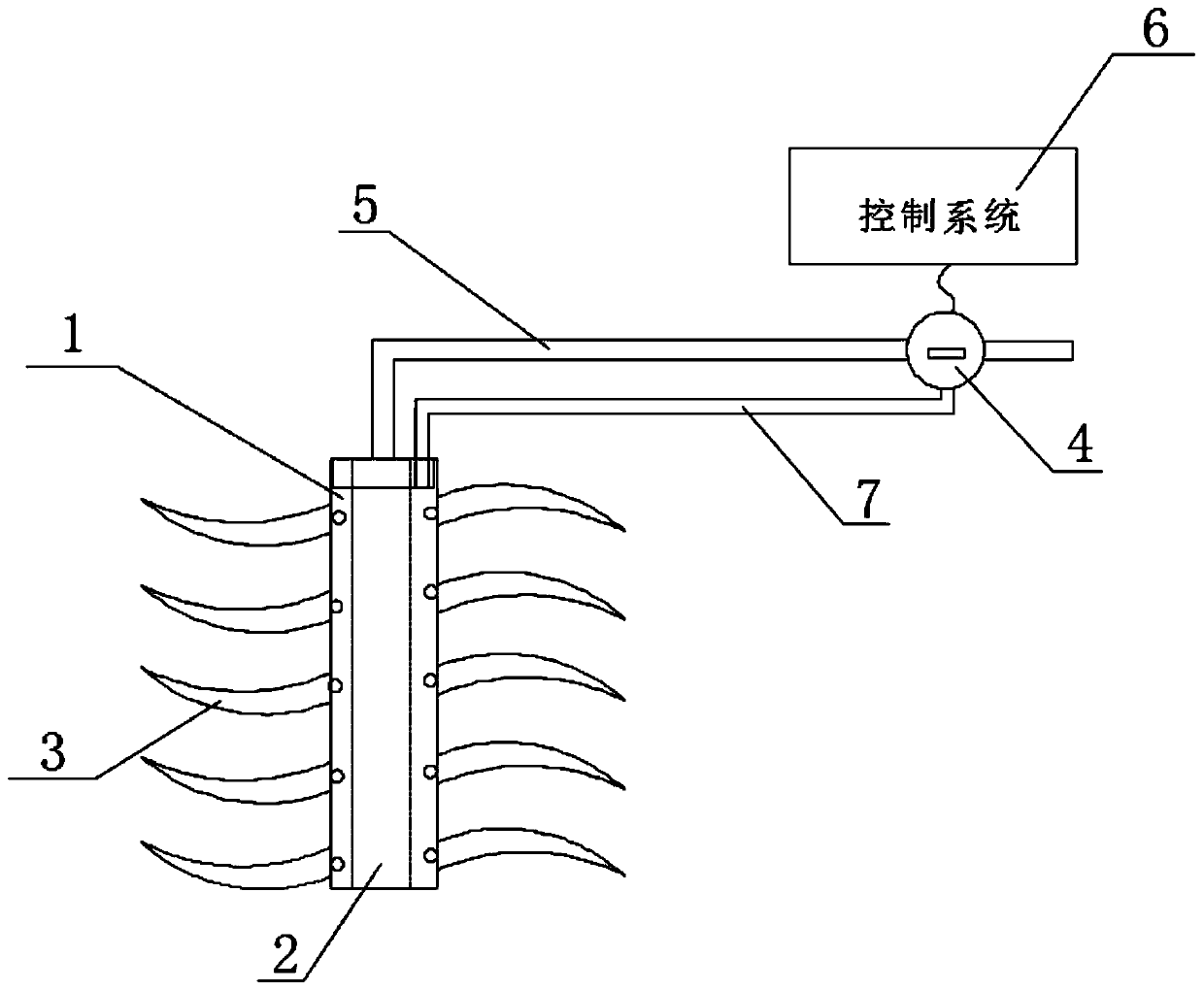
[0028] Such as figure 1 As shown, this embodiment provides a cutter suction dredger reamer device, including a reamer head 3, a mud pump 2, and a control system 6; a plurality of reamer heads 3 are located on the outer periphery of the reamer cylinder; The mud pump 2 is located inside the reamer barrel; the reamer barrel is rotated around the mud pump 2; the mud pump 2 is connected to the delivery pipeline 5; the mud pump 2 is electrically connected to the control system 6; A gap is provided, and the gap is a compression chamber 1, and a plurality of holes are arranged on the surface of the compression chamber 1, and a steering valve 4 is arranged on the delivery pipeline 5, and the branch end of the steering valve 4 is connected to the return water pipeline 7, The return water pipe 7 is connected to the compression chamber 1 and communicates with the inside of the compression chamber 1 .

[0029] During specific implementation, the return water pipe 7 is connected to the top...

Embodiment 2

[0031] During specific implementation, the steering valve 4 is a manual valve. The steering valve 4 is located near the water outlet on the delivery pipeline 5 .

[0032] Steering valve 4 is a ball valve or a butterfly valve etc., as long as the junction that can realize the function of protecting the nib is within the protection scope of the present invention, the outer sidewall of the pen cap can be polygonal or circular.

Embodiment 3

[0034] On the basis of Embodiment 1, the steering valve 4 is an electric valve, and the steering valve 4 is electrically connected to the control system 6, and the control system 6 includes a control switch of the steering valve 4 . When the electric valve is used, it is usually enough to directly connect to the transformed power supply, and the electric valve with a built-in transformer can be directly connected to the power supply, which is convenient for implementation. Electric valves are usually composed of electric actuators and valves. The electric valve uses electric energy as power to drive the valve through the electric actuator to realize the switching action of the valve. So as to achieve the purpose of switching the pipeline medium.

[0035] Solenoid valve can also be used. Solenoid valve is a type of electric valve; it uses the magnetic field generated by the electromagnetic coil to pull the valve core, thereby changing the on-off of the valve body. When the coi...


PUM


Abstract

The invention discloses a cutter suction dredge reamer device. The cutter suction dredge reamer device comprises a plurality of reamer heads, a slurry pump and a control system; the multiple reamer heads are located on the periphery of a reamer barrel; the slurry pump is located in the reamer barrel; the reamer barrel is rotatably arranged around the slurry pump; the slurry pump is connected witha conveying pipeline; and the slurry pump is electrically connected with the control system. The cutter suction dredge reamer device is characterized in that a gap is arranged between the reamer barrel and the slurry pump, the gap is a compression cavity, a plurality of holes are formed in the surface of the compression cavity, a steering valve is arranged on the conveying pipeline, the branch endof the steering valve is connected with a water return pipeline, and the water return pipeline is connected with the compression cavity and communicates with the interior of the compression cavity. The steering valve is started when the content of slurries is reduced, a water body pumped and sucked by the slurry pump is injected into the compression cavity through a reverse-flow system, the multiple holes are formed in the surface of the cavity, the water body entering through reverse flow is ejected through the holes, and the ejected high-velocity water flow can clean garbage on the reamer heads; and the problem that an existing cutter suction dredge reamer is prone to being blocked by wound by the garbage is solved.

Description

technical field [0001] The invention belongs to a reamer for a dredger, in particular to a cutter suction dredger reamer device. Background technique [0002] In the existing dredging process of rivers and lakes, cutter suction dredgers are generally used for underwater sediment dredging operations. However, due to the large amount of garbage in the rivers and lakes, especially the domestic garbage in urban rivers and lakes is relatively thick. Therefore, the reamer head is often entangled to death by domestic garbage during the operation of the dredger, which is not conducive to the development of dredging work. [0003] Under normal working conditions, after the control system on the dredger is turned on, the reamer head starts to work, agitating the bottom mud of rivers and lakes to form mud, which is sucked by the mud pump into the conveying pipeline, and finally sent to the mud pool where the mud is disposed of. However, once the reamer head is entangled by domestic g...

Claims


Application Information

Patent Timeline
Patent Type & Authority Applications(China)
IPC IPC(8): E02F3/92
CPCE02F3/9275
Inventor 陈澍
Owner 武汉澄川朗境环境科技有限公司
Why Eureka
Try Eureka