
Sponge city water drainage and water seepage structure and rainwater collection and utilization system and working method

A rainwater collection and water seepage structure technology, applied in waterway systems, drainage structures, roof drainage, etc., can solve the problems of destroying the natural ecological background, loss of sponge effect, frequent waterlogging disasters, etc., to achieve recycling and reuse, structure Reasonable design and the effect of improving utilization

Pending Publication Date: 2020-06-09
CHINA SHANXI SIJIAN GRP
View PDF0 Cites 10 Cited by
  • Summary
  • Abstract
  • Description
  • Claims
  • Application Information

AI Technical Summary

Problems solved by technology

After urban development and construction, due to the hardening of the underlying surface caused by the construction of roofs, roads, squares and other facilities, 70% to 80% of the rainfall forms rapid runoff on the surface, and only 20% to 30% of the rainwater can penetrate into the ground. The hydrological phenomenon that is contrary to nature not only destroys the natural ecological background, but also makes the natural "sponge body" like a hood, and loses the "sponge effect", resulting in "every rain will be waterlogged, and there will be drought after rain"; at the same time , also brought a series of problems such as deterioration of water ecology, shortage of water resources, water environment pollution, frequent occurrence of waterlogging disasters, etc.

Method used


Image

  • Sponge city water drainage and water seepage structure and rainwater collection and utilization system and working method
  • Sponge city water drainage and water seepage structure and rainwater collection and utilization system and working method
  • Sponge city water drainage and water seepage structure and rainwater collection and utilization system and working method

Examples


Embodiment Construction

[0033] In order to enable those skilled in the art to better understand the present invention, the present invention will be further clearly and completely described below in conjunction with reference to the accompanying drawings and in conjunction with embodiments. It should be noted that, in the case of no conflict, the embodiments in the present application and the features in the embodiments can be combined with each other.

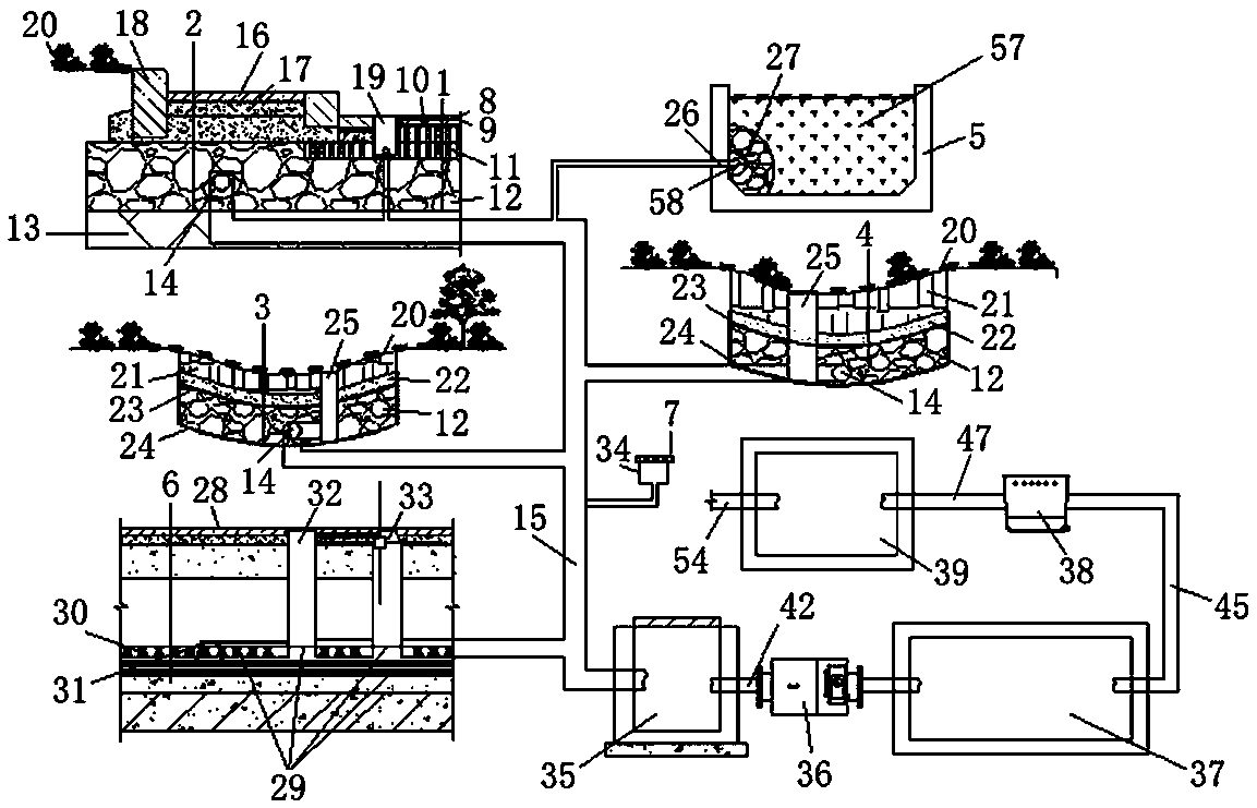
[0034] like Figure 1 to Figure 3 As shown, a sponge city drainage structure and rainwater collection and utilization system includes a drainage structure and a rainwater collection structure.

[0035] The seepage drainage structure includes road layer structure 1, sidewalk structure 2, greening structure 3, sunken green space structure 4, flower pond and tree pond structure 5, pavement surface structure 6 and roof 7.

[0036] The road layer structure 1 includes a permeable asphalt concrete layer 8, a waterproof seal layer 9, a medium-grained asphal...


PUM

PropertyMeasurementUnit
Maximum particle sizeaaaaaaaaaa
Diameteraaaaaaaaaa

Abstract

The invention relates to a sponge city water drainage and water seepage structure and rainwater collection and utilization system and a working method thereof. The sponge city water drainage and waterseepage structure and rainwater collection and utilization system comprises a water drainage and water seepage structure and a rainwater collection structure. According to the sponge city water drainage and water seepage structure and rainwater collection and utilization system, through structural layers with high permeability, rainwater is easy to penetrate into a flow guiding pipe in a naturalgraded crushed stone layer, flows into a safe flow dividing well through a rainwater drainage pipe which is connected with the flow guiding pipe and enters a glass reinforced plastic reservoir throughthe pretreatment of a flow removal controller, after being purified by an underground integrated machine, the rainwater enters a glass reinforced plastic clear water tank to reduce the ponding on thepavement surface, roads, green areas and the like, and the rainwater can be used for fire fighting, greening and other water use after sedimentation and purification, so that the utilization rate ofthe rainwater is improved, and water resources are saved.

Description

technical field [0001] The invention relates to the technical field of sponge cities, in particular to a sponge city drainage structure, a rainwater collection and utilization system and a working method thereof. Background technique [0002] The natural underlying surface itself is a huge sponge, which has the sponge effect of absorbing, infiltrating and storing rainfall, thus playing a certain role in controlling the runoff of rainwater. When the rainfall reaches saturation through the absorption, infiltration and stagnation of the underlying surface, it will be discharged naturally through surface runoff. After urban development and construction, due to the hardening of the underlying surface caused by the construction of roofs, roads, squares and other facilities, 70% to 80% of the rainfall forms rapid runoff on the surface, and only 20% to 30% of the rainwater can penetrate into the ground. The hydrological phenomenon that is contrary to nature not only destroys the na...

Claims


Application Information

Patent Timeline
IPC IPC(8): E03B3/02E01C11/22E03F5/04E03F5/046E03F5/10E04D13/04E04D13/08
CPCE01C11/223E01C11/224E01C11/225E01C11/226E03B3/02E03F5/04E03F5/0401E03F5/046E03F5/10E04D13/04E04D13/08Y02A20/108
Inventor 刘立峰高小荣牛艳琴李正杨振广任义李妙平
Owner CHINA SHANXI SIJIAN GRP
Learn More