Oil-water separation device for vacuum pump

A technology of oil-water separation device and vacuum pump, which is applied to the components, separation methods, and separation of dispersed particles of elastic fluid pumping devices, and can solve problems such as poor cooling effect, polluted air, and insufficient separation, and achieve structural Simple and practical, avoiding pollution, ingenious effect

Inactive Publication Date: 2020-06-12
魏九宝
View PDF0 Cites 0 Cited by
  • Summary
  • Abstract
  • Description
  • Claims
  • Application Information

AI Technical Summary

Problems solved by technology

[0005] The object of the present invention is to address the deficiencies of the prior art, and provide an oil-water separation device for a vacuum pump. By setting a separation box and a separation mechanism, the gas enters the separation box and directly acts on the end of the separation component of the separation mechanism to drive each The separation assembly rotates in the separation box, and the gas in the separation space formed by two adjacent separation assemblies rotates with it during the rotation, so that the gas stays in the separation box for a long time and the separation assemblies on both sides are opposite to the separation space. The exhaust gas is fully cooled, and the exhaust gas is clean to avoid air pollution, thereby solving the problem that the existing equipment has poor cooling effect and insufficient separation when cooling and separating the exhaust gas, and the exhaust gas contains oil and impurities. air pollution problem

Method used


Image

  • Oil-water separation device for vacuum pump
  • Oil-water separation device for vacuum pump
  • Oil-water separation device for vacuum pump

Examples


Embodiment 1

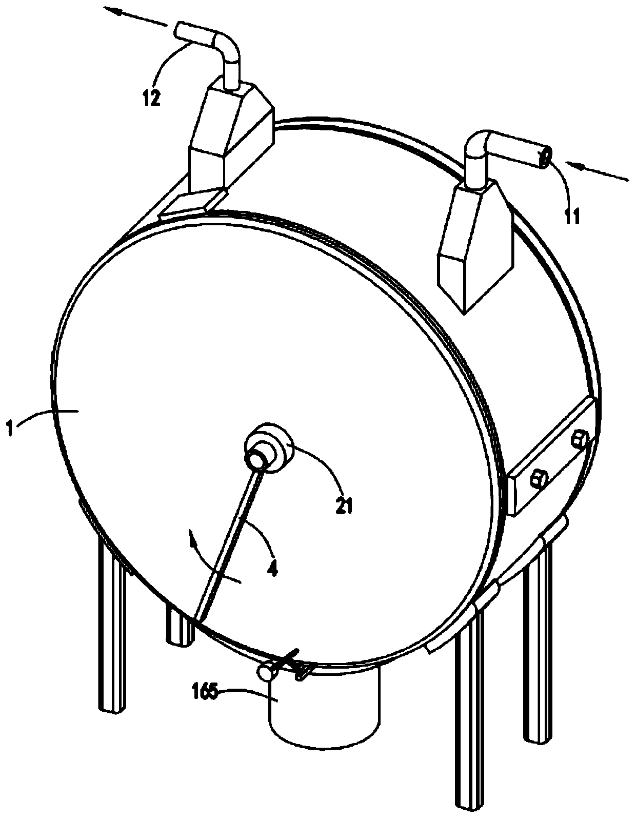
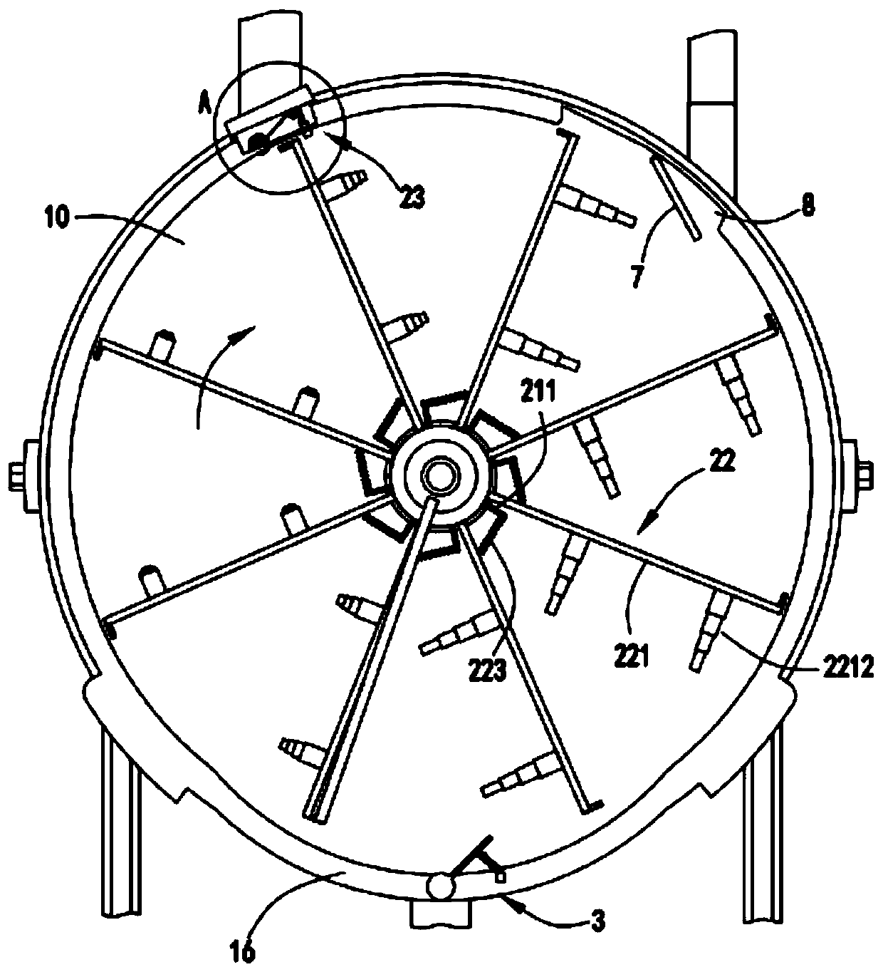
[0038] Such as Figure 1 to Figure 11 As shown, an oil-water separation device for a vacuum pump includes a separation box 1, the separation box 1 is connected with an air inlet pipe 11 and an air outlet pipe 12; the separation box 1 is provided with a separation mechanism 2, and the separation mechanism 2 It includes a rotating shaft 21 and a number of separation assemblies 22 arranged on the rotating shaft 21. A separation space 10 is formed between two adjacent separation assemblies 22. The air inlets 13 connected to the air inlet pipe 11 and the air outlet pipe 12 on the separation box 1 are respectively and the gas outlet 14 are respectively located on the left and right sides of the central axis of the separation box 1, the oil-containing gas enters the separation box 1 through the inlet pipe 11 and the air inlet 13, and the oil-containing gas acts on the separation assembly 22 located below the air inlet 13 to drive the rotating shaft 21 rotates so as to drive each sepa...

Embodiment 2

[0050] Such as Figure 8 and Figure 11 As shown, the components that are the same as or corresponding to those in the first embodiment are marked with the corresponding reference numerals in the first embodiment. For the sake of simplicity, only the differences from the first embodiment will be described below. The difference between the second embodiment and the first embodiment is that: the bottom of the separation box 1 is also provided with an oil discharge assembly 3, and the oily liquid condensed in the separation box 1 is collected to the oil discharge assembly 3, and the oil discharge assembly 3 The oil component 3 is intermittently communicated with the outside by means of the rotation of the rotating shaft 21 to discharge the oily liquid.

[0051] Further, the bottom of the separation box 1 is provided with an arc-shaped groove portion 16, and the middle bottom of the arc-shaped groove portion 16 is provided with a rotating groove 161, and the oil discharge assembl...


PUM


Abstract

The invention relates to an oil-water separation device for a vacuum pump. The oil-water separation device comprises a separation box, and the separation box is connected with a gas inlet pipe and a gas outlet pipe; a separation mechanism is arranged in the separation box and comprises a rotating shaft and a plurality of separation assemblies, a separation space is formed between every two adjacent separation assemblies, oil-containing gas enters the separation box through the gas inlet pipe and the gas inlet, and the oil-containing gas acts on the separation assemblies located below the gas inlet to drive the rotating shaft to rotate so as to drive all the separation assemblies to rotate together; when the separation space rotates to the gas outlet along with the separation assemblies, the two adjacent separation assemblies forming the separation space gradually get close to each other, gas in the separation space is extruded out of the gas outlet, oil gas in the separation space is cooled in the rotating process, and oil-containing liquid is condensed and flows out of the bottom of the separation box. The problems that when existing equipment cools and separates exhausted gas, the cooling effect is poor, separation is insufficient, and the exhausted gas contains oil and impurities and pollutes gas are solved.

Description

technical field [0001] The invention relates to the technical field of vacuum pumps, in particular to an oil-water separation device for vacuum pumps. Background technique [0002] Vacuum oil is needed in the vacuum pump. The vacuum oil is vaporized and discharged with the gas. The sea contains moisture and other impurities. The gas needs to be cooled and separated. On the one hand, the discharged gas is clean and does not pollute the air. On the other hand, the condensed liquid can also be separated. oil for recycling. [0003] The authorized announcement number is a Chinese invention patent of CNB, which discloses a water and sewage treatment device for a slide valve vacuum pump. The slide valve vacuum pump includes a pump assembly and an oil sump box for vacuum pumping. The oil pool box is connected, and an oil-gas separator is arranged above the oil-gas discharge port. The water sewage treatment device includes a closed auxiliary oil tank connected to the exhaust port o...

Claims


Application Information

Patent Timeline
Patent Type & Authority Applications(China)
IPC IPC(8): B01D53/00B01D5/00F04C29/00
CPCB01D5/00B01D53/002F04C29/0092
Inventor 魏九宝
Owner 魏九宝
Why Eureka
Try Eureka