Oil storage tank mechanical cleaning and sump oil purifying system and method

A mechanical cleaning and purification system technology, applied in cleaning methods and appliances, chemical instruments and methods, cleaning hollow objects, etc., can solve problems such as the flow mismatch between the cleaning system and the purification system, improve disposal efficiency, improve purification efficiency, The effect of simple process

Pending Publication Date: 2020-06-12
杰瑞邦达环保科技有限公司
View PDF0 Cites 0 Cited by
  • Summary
  • Abstract
  • Description
  • Claims
  • Application Information

AI Technical Summary

Problems solved by technology

[0003] The object of the present invention overcomes the deficiencies of the prior art, and provides a kind of oil storage tank mechanical cleaning dirty oil purification system, which is provided with a cleaning system and a purification system, and the cleaning system and the purification system are connected through a valve, and the purification system is cleaned while circulating. Liquid supply can realize the purification of dirty oil in the cleaning process of the same kind of oil without stopping the cleaning; at the same time, the cleaning system and the purification system can be used separately or in a complete set; the flow rate of the cleaning system and the purification system can be solved by setting the buffer unit In the case of mismatching problems, the two systems can be carried out simultaneously to improve the disposal efficiency; by testing the solid content of the dirty oil entering the purification system, and limiting the solid content of 8%-15% of the dirty oil to enter the purification system, to ensure The effective and continuous operation of the dirty oil purification system improves the quality of the purified oil; by setting up a sedimentation separation unit, the purification efficiency is further improved and the purity of the purified oil is improved

Method used


Image

  • Oil storage tank mechanical cleaning and sump oil purifying system and method

Examples


Embodiment Construction

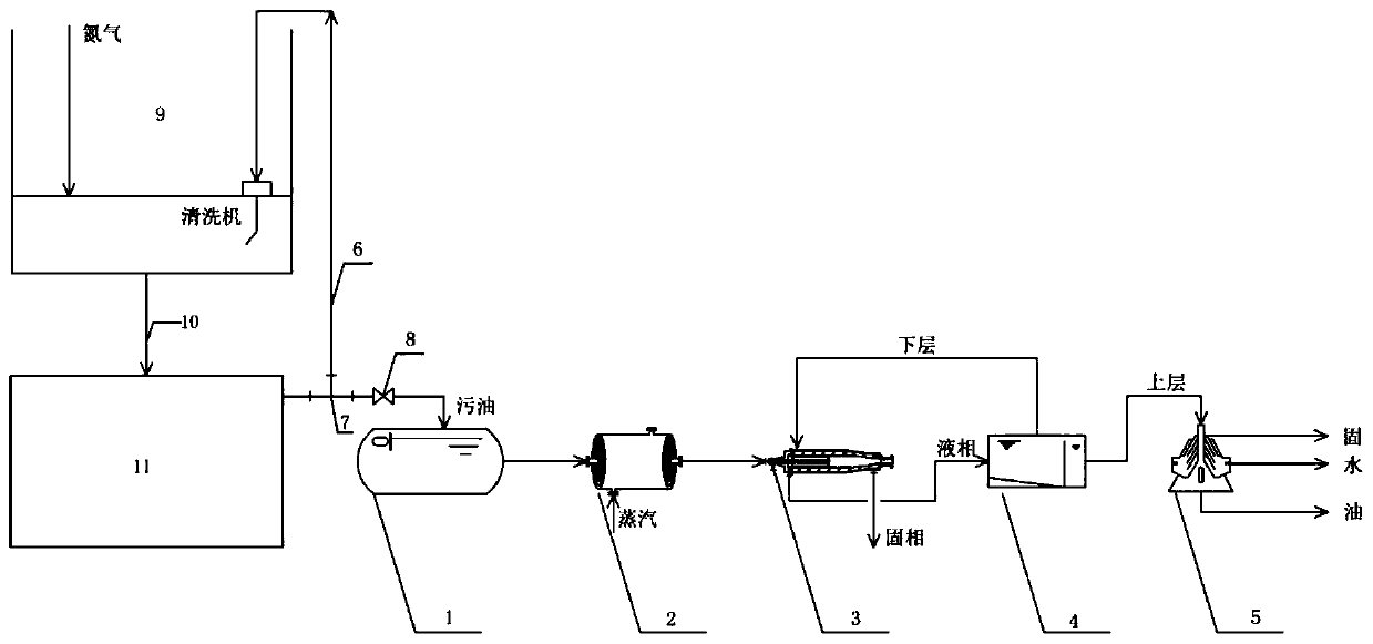
[0024] like figure 1 As shown, an oil storage tank mechanical cleaning dirty oil purification system includes a cleaning system and a purification system. The cleaning system includes an oil storage tank 9 and a mechanical cleaning device 11. The purification system includes a buffer unit 1 and a heat exchange unit 2. , a two-phase horizontal centrifugal unit 3, a settling separation unit 4 and a three-phase disc centrifugal unit 5, the oil storage tank 9 is connected to the inlet of the mechanical cleaning device 11 through a recovery pipeline 10, and the mechanical cleaning device 11 The outlet is divided into two paths through the tee 7, and one path is connected to the oil storage tank 9 through the cleaning pipeline 6. Further preferably, a cleaning machine is provided in the oil storage tank 9, and the mechanical cleaning device 11 includes a vacuum suction device , pressure pumping equipment and heat exchangers. The vacuum suction equipment sucks the dirty oil from the...


PUM


Abstract

The invention discloses an oil storage tank mechanical cleaning and sump oil purifying system. The oil storage tank mechanical cleaning and sump oil purifying system comprises a cleaning system and apurifying system; the cleaning system involves an oil storage tank and a mechanical cleaning device; and the purifying system involves a temporary storage unit, a heat exchange unit, a two-phase horizontal centrifugal unit, a settling separating unit and a three-phase disc type centrifugal unit. According to the oil storage tank mechanical cleaning and sump oil purifying system, the cleaning system and the purifying system are arranged, the cleaning system and the purifying system are connected through a valve, and liquid is supplied to the purifying system while circulating cleaning is carried out, so that sump oil purifying in the same oil cleaning link is achieved under the condition that cleaning is not stopped; meanwhile, the cleaning system and the purifying system can be separatelyused and can also be matched in set to be used; by arranging the temporary storage unit, the problem that the flow of the cleaning system is not matched with the flow of the purifying system can be solved, the two systems simultaneously operate, and the disposal efficiency is improved; and the cleaning system and the purifying system are physical separating processes, chemical agents do not need to be added, the secondary pollution cannot be caused to oil products, and the working procedures are simple.

Description

technical field [0001] The invention relates to the technical field of oil field environmental protection, in particular to a system and method for mechanically cleaning dirty oil of an oil storage tank. Background technique [0002] During the long-term storage and production of the oil tank, a small amount of mechanical impurities, sand, soil, heavy metal salts, and heavy oily components such as paraffin and asphalt in the oil will naturally settle due to the difference in specific gravity and accumulate at the bottom of the oil tank, forming The black and thick gelatinous substance layer is the oil tank bottom mud. Oil tank bottom sludge increases with the increase of continuous storage and transportation time. Over time, it will seriously affect the storage and transportation production of oil tanks and must be removed regularly. At present, the general oil tank mechanical cleaning system in China is COWS (Crude Oil Washing System) crude oil washing system. The traditi...

Claims


Application Information

Patent Timeline
IPC IPC(8): B08B9/08B08B9/093
CPCB08B9/0804B08B9/0813
Inventor 衣桂米张海秀肖超王聪毛
Owner 杰瑞邦达环保科技有限公司
Why Eureka
Try Eureka