
Expansion tank for water supply system of plate type heat exchanger unit

A water supply system and plate heat exchange technology, applied in the field of expansion tanks, can solve the problems of reducing the drainage effect of the expansion tank, affecting the drainage effect of the expansion tank, and affecting the service life of the expansion tank, so as to improve the drainage effect, increase the uniformity of pressure, The effect of increasing the service life

Inactive Publication Date: 2020-06-12
乐沃(天津)新能源技术有限公司
View PDF0 Cites 1 Cited by
  • Summary
  • Abstract
  • Description
  • Claims
  • Application Information

AI Technical Summary

Problems solved by technology

[0004] 1. Most of the bladders used in the current expansion tanks are spherical bladders and cylindrical bladders. When the water in this type of bladder contacts the gas, only one side receives the pressure of the gas, so that the side far away from the gas The pressure of the gas on the side will be relatively small, which will easily cause the instability of the local water pressure inside the tank, which will further affect the drainage effect of the expansion tank;
[0005] 2. The current expansion tank often produces some vibrations when it is working. When the tank body is subjected to vibration for a long time, it will affect the service life of the expansion tank, thereby reducing the drainage effect of the expansion tank.

Method used


Image

  • Expansion tank for water supply system of plate type heat exchanger unit
  • Expansion tank for water supply system of plate type heat exchanger unit
  • Expansion tank for water supply system of plate type heat exchanger unit

Examples


Embodiment Construction

[0020] The following will clearly and completely describe the technical solutions in the embodiments of the present invention with reference to the accompanying drawings in the embodiments of the present invention. Obviously, the described embodiments are only some, not all, embodiments of the present invention. Based on the embodiments of the present invention, all other embodiments obtained by persons of ordinary skill in the art without making creative efforts belong to the protection scope of the present invention.

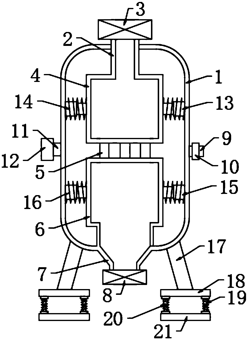
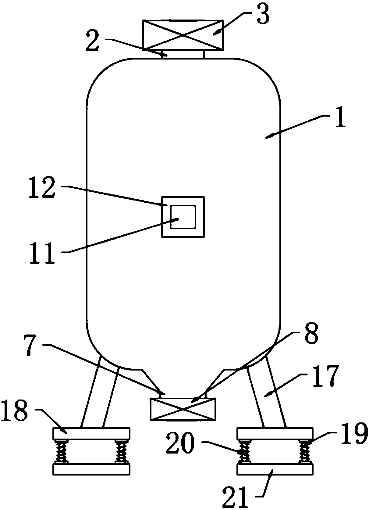
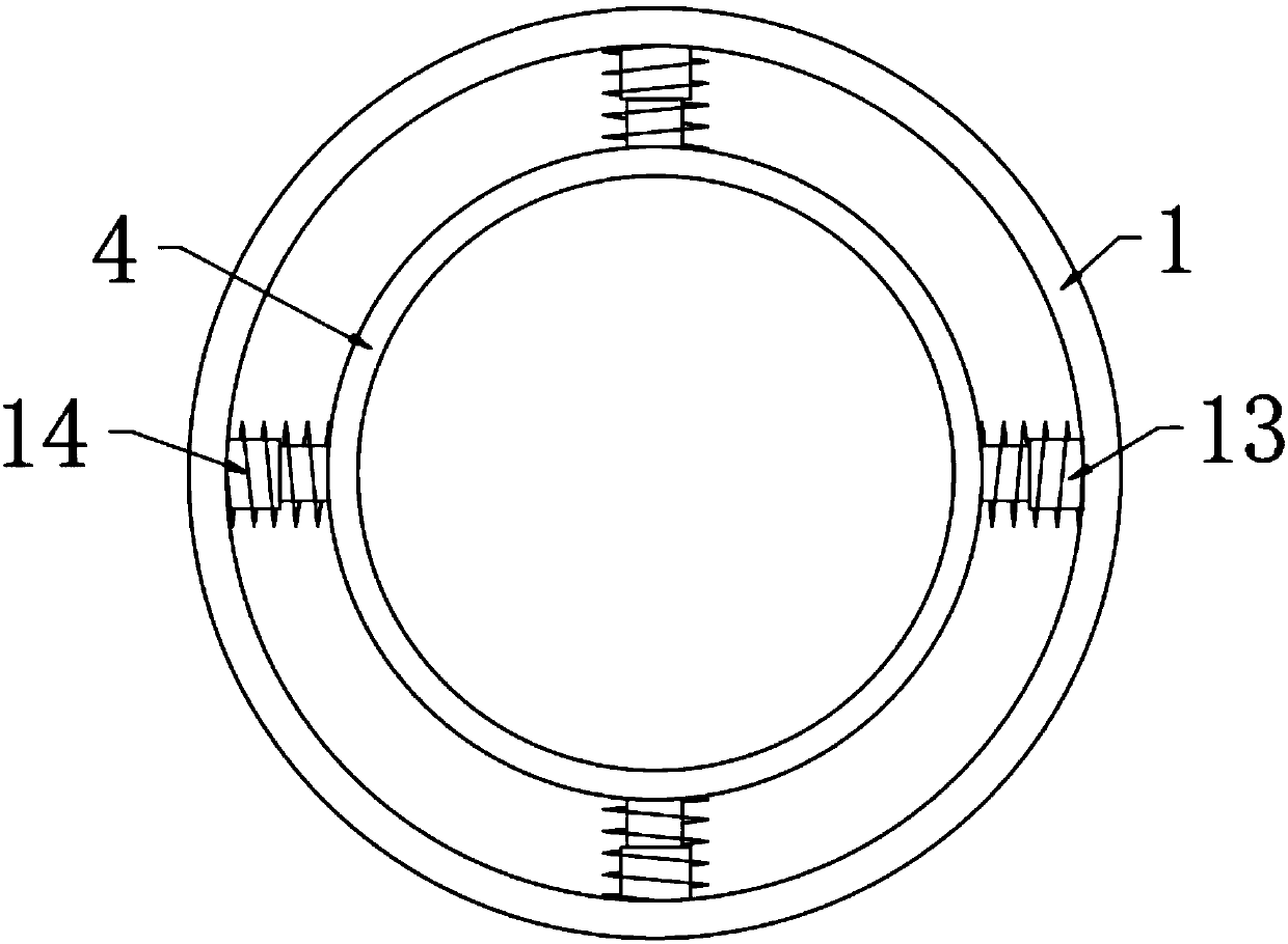
[0021] see Figure 1-3 , the present invention provides a technical solution: an expansion tank for a water supply system of a plate heat exchange unit, comprising a tank body 1, the top of the tank body 1 is fixedly provided with a water inlet pipe 2, and the water inlet pipe 2 is far away from the tank body One end of 1 is fixedly provided with a first electromagnetic valve 3, and the inside of the tank body 1 is provided with a first bladder chamber 4 below...


PUM


Abstract

The invention discloses an expansion tank for a water supply system of a plate type heat exchanger unit. The expansion tank comprises a tank body, wherein a water inlet pipe is fixedly mounted at thetop of the tank body, a first electromagnetic valve is fixed to the end, away from the tank body, of the water inlet pipe, a first skin bag chamber is formed in the position, located below the water inlet pipe, in the tank body, a plurality of water delivery skin bag pipes are uniformly arranged at the bottom of the first skin bag chamber, a second skin bag chamber is fixed to the ends, away fromthe first skin bag chamber, of the water delivery skin bag pipes, and is located in the tank body, a drain pipe is fixed to the bottom of the second skin bag chamber, and a second electromagnetic valve is fixed to the end, away from the tank body, of the drain pipe. By means of the first skin bag chamber and the second skin bag chamber, the contact area of gas and water can be increased, water canbe subjected to relatively uniform pressure bearing during draining, so that pressing uniformity of water in the first skin bag chamber and the second skin bag chamber is increased, and the drainingeffect of the expansion tank is improved.

Description

technical field [0001] The invention relates to the technical field of expansion tanks, in particular to an expansion tank used for a water supply system of a plate heat exchange unit. Background technique [0002] Expansion tank, when water with pressure from the outside enters the expansion tank air bag, the nitrogen sealed in the tank is compressed, according to Boyle's gas law, the gas volume becomes smaller after compression and the pressure increases until the gas pressure in the expansion tank is equal to Stop water inflow when the water pressure reaches a consistent level. When the water loss pressure decreases, the gas pressure in the expansion tank is greater than the water pressure, and the gas expands to squeeze out the water in the air bag to replenish the system. [0003] Current household grain storage has the following deficiencies: [0004] 1. Most of the bladders used in the current expansion tanks are spherical bladders and cylindrical bladders. When the...

Claims


Application Information

Patent Timeline
IPC IPC(8): E03B7/09
CPCE03B7/09
Inventor 张辉赵贺
Owner 乐沃(天津)新能源技术有限公司
Learn More