Weak ocean current power system for energy supplement for deep sea subsurface buoy
A power generation system and energy technology, applied in the directions of hydroelectric power generation, reaction engine, engine components, etc., can solve the problems of flow velocity fluctuation and lack of practicability, achieve uniform load torque, improve energy capture efficiency, and improve efficiency.
- Summary
- Abstract
- Description
- Claims
- Application Information
AI Technical Summary
Problems solved by technology
Method used
Image
Examples
Embodiment 1
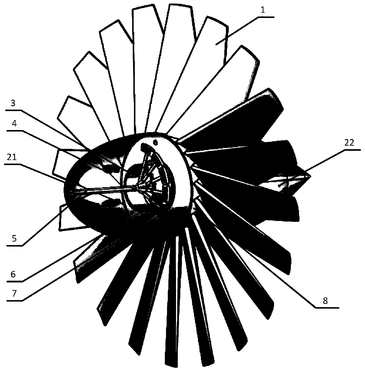
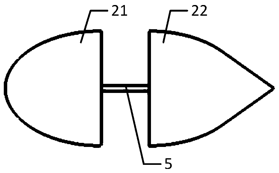
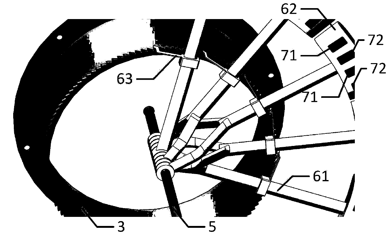
[0038] The power generation system includes: impeller structure and power generation structure. Wherein, the maximum diameter of the impeller structure is 3m, including the central shaft 5, the first dome 21, the second dome 22 and the impeller hub 8; the first dome 21 and the second dome 22 are fixed on the central shaft 5 Above; the impeller hub 8 is located between the first shroud 21 and the second shroud 22 , and is rotatably fixed on the central shaft 5 ; 20 blades 1 are arranged on the impeller hub 8 . The side of the impeller hub 8 facing the first shroud 21 is provided with a ratchet 3 .
[0039] Specifically, the maximum diameter of the first shroud 21 and the second shroud 22 is 1 m, and the axial friction circle radius between the central shaft 5 and the impeller hub 8 is 15 mm. The central shaft 5 is made of stainless steel, the impeller hub 8 is made of polyoxymethylene, the friction coefficient of the two materials is 0.1, the water absorption is less than 0.05...
Embodiment 2
[0045] The power generation system includes: impeller structure and power generation structure. Wherein, the maximum diameter of the impeller structure is 3m, including the central shaft 5, the first dome 21, the second dome 22 and the impeller hub 8; the first dome 21 and the second dome 22 are fixed on the central shaft 5 Above; the impeller hub 8 is located between the first shroud 21 and the second shroud 22 , and is rotatably fixed on the central shaft 5 ; 20 blades 1 are arranged on the impeller hub 8 . The side of the impeller hub 8 facing the first shroud 21 is provided with a ratchet 3 .
[0046] Specifically, the maximum diameter of the first shroud 21 and the second shroud 22 is 1 m, and the axial friction circle radius between the central shaft 5 and the impeller hub 8 is 15 mm. The central shaft 5 is made of stainless steel, the impeller hub 8 is made of polyoxymethylene, the friction coefficient of the two materials is 0.1, the water absorption is less than 0.05...
PUM
| Property | Measurement | Unit |
|---|---|---|
| Diameter | aaaaa | aaaaa |
| Elastic modulus | aaaaa | aaaaa |
Abstract
Description
Claims
Application Information
 - R&D
- Intellectual Property
- Life Sciences
- Materials
- Tech Scout
- Unparalleled Data Quality
- Higher Quality Content
- 60% Fewer Hallucinations
Browse by: Latest US Patents, China's latest patents, Technical Efficacy Thesaurus, Application Domain, Technology Topic, Popular Technical Reports.
© 2025 PatSnap. All rights reserved.Legal|Privacy policy|Modern Slavery Act Transparency Statement|Sitemap|About US| Contact US: help@patsnap.com


