Power supply and oven integrated cabinet test system

A test system and integrated technology, applied in control/regulation system, environment/reliability test, electrical measurement, etc., can solve the problem of affecting the reliability and accuracy of test results, affecting the cost of test space and time, and affecting test progress Efficiency and other issues to achieve the effect of reducing time cost and economic cost, increasing convenience and reducing test cost

Pending Publication Date: 2020-06-12
深圳市泰欣能源科技有限公司
View PDF0 Cites 0 Cited by
  • Summary
  • Abstract
  • Description
  • Claims
  • Application Information

AI Technical Summary

Problems solved by technology

[0004] 1. The test chambers in the prior art are all small test chambers, which limit the size of the battery to be tested and the number of samples to be tested at the same time, which affects the efficiency of the test;
[0005] 2. In the prior art, the sample to be tested is loaded on the tray, and the surface of the sample contacting the tray cannot be in good contact with the environment, which affects the test results;
[0006] 3. In the existing technology, the power module and the test box are placed separately, and need to be moved back and forth when moving and adjusting, which affects the cost of the test area and time
[0007] In addition, at present, the output load of the power module test device at home and abroad adopts two modes: 1. Directly use resistance as the load. For different output specifications, different load resistances need to be replaced, which is very inconvenient, and all output power is converted into heat consumption; 2. Consumable electronic loads are used, which can be programmed to adapt to different output specifications, but the output power is still converted into heat consumption
The energy conversion efficiency of the power module itself is above 80%. It can be seen that the main power consumption during the test is converted into heat and wasted in vain. At the same time, due to the large heat generation, it will in turn affect the ambient temperature and affect the reliability and accuracy of the test results.

Method used


Image

  • Power supply and oven integrated cabinet test system
  • Power supply and oven integrated cabinet test system
  • Power supply and oven integrated cabinet test system

Examples


Embodiment Construction

[0036] In order to make the object, technical solution and advantages of the present invention clearer, the present invention will be further described in detail below in conjunction with the accompanying drawings and embodiments. It should be understood that the specific embodiments described here are only used to explain the present invention, not to limit the present invention.

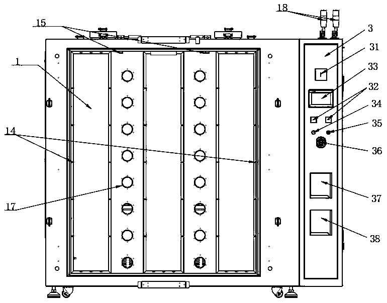
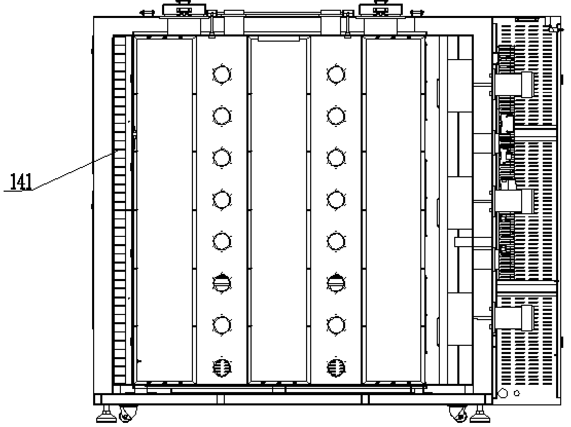
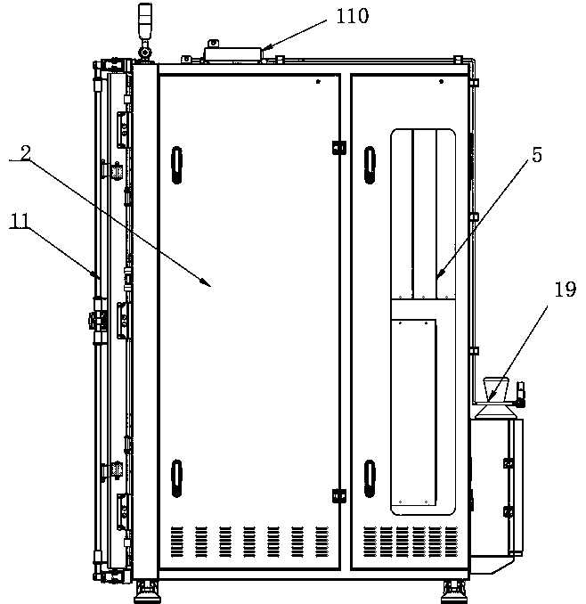
[0037] see figure 1 As for image 3 ,in, figure 1 It is a schematic diagram of the front structure of the power oven integrated cabinet test system according to the embodiment of the present invention; figure 2 It is a schematic diagram of the internal structure of the power oven integrated cabinet test system according to the embodiment of the present invention; image 3 It is a schematic diagram of the structure on the right side of the power oven integrated cabinet test system according to the embodiment of the present invention. The test system for an integrated cabinet with power supply a...


PUM


Abstract

The invention belongs to the technical field of test equipment, and particularly relates to a power supply and oven integrated cabinet test system. The system comprises a test chamber, an electric appliance chamber, a control panel and an energy feedback type power supply module, and the electric appliance chamber and the control panel are arranged at the right side of the test chamber; the energyfeedback type power supply module is arranged at the rear side of the test chamber; a wind wheel and a heating disc are arranged in the test chamber, the heating disc is located in front of the windwheel, a motor is further arranged on the outer side of the test chamber, and the wind wheel is connected with the motor. A PLC is arranged in the electric appliance chamber, the motor and the heatingdisc are connected with the PLC, and the PLC is connected with the control panel. A support frame for placing a to-be-tested power supply module is also arranged in the test chamber; and the energy feedback type power supply module is connected with the to-be-tested power supply module. The test box and the power supply module are integrated, the space is saved, the arrangement and the use are convenient, and the test cost is saved.

Description

technical field [0001] The invention relates to the technical field of test equipment, in particular to a test system for a power supply oven integrated cabinet. Background technique [0002] With the improvement of quality requirements for industrial products, the products produced need to undergo simulation tests before they are put into the market, and the tests are required to completely and truly simulate the real situation of the products during use. The oven test chamber is widely used in the field of performance testing. Its main function is to test the performance of products in different temperature environments. Among them, the performance testing of batteries occupies an important position, so that the reliability of products in different temperature environments can meet the requirements. [0003] There are still various problems in the existing technology that need to be solved urgently in the oven test chamber for constant temperature test of product parts, as...

Claims


Application Information

Patent Timeline
Patent Type & Authority Applications(China)
IPC IPC(8): G01R31/00G01R31/385B01L1/00A62C3/16G05D23/22
CPCA62C3/16B01L1/00G01R31/003G01R31/385G05D23/22
Inventor 盛玮东黄昕昊
Owner 深圳市泰欣能源科技有限公司
Why Eureka
Try Eureka