
Nonlinear frequency stepping method and system for stepping frequency radar

A technology of frequency stepping and stepping frequency, applied in the field of nonlinear frequency stepping method and its system, can solve the problems of low flexibility limiting the adaptability of radar system, low visibility of transmitted signal, and generating grating lobe effect.

Active Publication Date: 2020-06-12
CENT SOUTH UNIV
View PDF7 Cites 5 Cited by
  • Summary
  • Abstract
  • Description
  • Claims
  • Application Information

AI Technical Summary

Problems solved by technology

However, traditional radar systems are usually designed for specific application scenarios, and it is difficult to adapt to changing detection scenarios
That is to say, the low flexibility of fixed hardware limits the adaptability of the radar system to the changing working environment. The resulting problems include: the visibility of the actual transmitted signal is low, it is difficult to flexibly encode and decode the signal, Unable to achieve adaptive adjustment of transmitted signal power and bandwidth, etc.
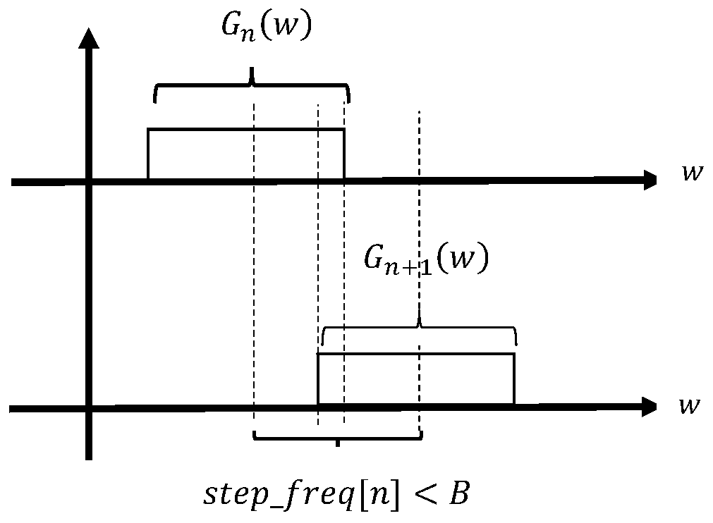
This method reduces the number of frequency steps and improves the efficiency of radar measurement, but it will produce grating lobe effects and cause false targets

Method used


Image

  • Nonlinear frequency stepping method and system for stepping frequency radar
  • Nonlinear frequency stepping method and system for stepping frequency radar
  • Nonlinear frequency stepping method and system for stepping frequency radar

Examples


Embodiment 1

[0069] This embodiment has adopted a kind of simulation experiment, carries out the chirp radar simulation experiment in the matlab environment, sets the detection scene as two point targets, is located at 100m and 110m respectively, the RCS (Radar Cross-Section, radar cross-section) of two targets Scattering cross-sectional area) is the same. First, the conventional non-interval scanning method is adopted. The frequency scanning interval is [1, 2.6] GHz, the total bandwidth is 1.6 GHz, and a total of 10 sub-bands are set, and the bandwidth of each sub-band is 160 MHz. Within each sub-band, a chirp signal is used to scan and extract target echoes. The synthesized broadband spectrum and 1D range image over the entire frequency sweep interval are shown as Figure 6 shown. Depend on Figure 6 (a) and Figure 6 (b) It can be seen that there is no gap between the sub-bands when using conventional frequency sweep at equal intervals, and the broadband composite spectrum can be ob...

Embodiment 2

[0074] In this embodiment, a USRP X310 software defined radio device is used for actual measurement experiments. In this system, the hardware device adopts USRP X310, the sub-board model is UBX-160, supports 160MHz radio frequency bandwidth, the tuning range is 60MHz-6GHz, the antenna uses double-ridged horn antenna, the working frequency is 900MHz-2900MHz, and the software system uses GNU Radio Combined with UHD (USRP Hardwaredriver), use Matlab to process the collected data.

[0075] According to the frequency range of the horn antenna in the embodiment, the frequency scanning range used is 1.2GHz-2.8GHz, which is divided into 10 sub-bands, each sub-band uses a complete sub-board bandwidth of 160MHz, and the signal waveform is a chirp signal. ref n (t) with echo n (t) are the reference signal and the echo signal respectively. Where n=1,2,…,10, the waveform is a chirp signal, the time-domain sampling rate is 200Mhz, and the single-frequency point signal duration is 0.5ms, ...


PUM


Abstract

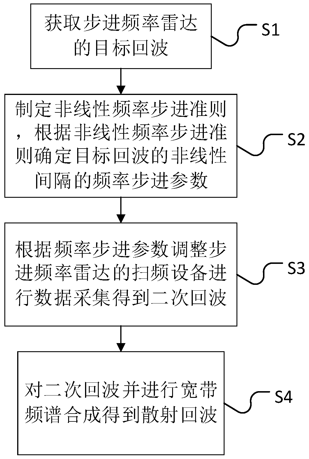
The invention provides a nonlinear frequency stepping method and system for a stepping frequency radar. The nonlinear frequency stepping method comprises a nonlinear frequency stepping criterion, a nonlinear interval broadband spectrum synthesis method and an implementation method of a nonlinear stepping frequency radar system based on a software radio platform. According to the method, radar echocharacteristics under a uniform stepping interval are analyzed; a nonlinear frequency stepping criterion is designed; and the detection area is scanned for the second time to obtain radar echoes, a broadband spectrum synthesis method under nonlinear frequency stepping is designed, and the broadband spectrum under nonlinear frequency stepping is synthesized to obtain radar scattering echoes, thereby achieving the purposes of improving the radar resolution and reducing the sidelobe of a one-dimensional range profile. Implementation schemes of the non-linear stepping frequency radar system basedon the software radio platform are provided, and the implementation schemes comprise a hardware building scheme and platform parameter configuration.

Description

technical field [0001] The invention relates to the field of radio waves, and specifically discloses a nonlinear frequency stepping method and system for stepping frequency radar. Background technique [0002] Radar is a device that realizes the perception and detection of the environment and targets through electromagnetic waves, and can realize the acquisition of one-dimensional range images and two-dimensional images of targets. The working system of radar is divided into frequency modulation continuous wave, impulse pulse, random noise and so on. Among them, frequency modulation continuous wave radar achieves target detection by transmitting frequency modulated signals, which has the advantages of low transmission power peak value, easy modulation, low cost, and simple signal processing. However, traditional radar systems are usually designed for specific application scenarios, and it is difficult to adapt to changing detection scenarios. That is to say, the low flexib...

Claims


Application Information

Patent Timeline
Patent Type & Authority Applications(China)
IPC IPC(8): G01S7/41
CPCG01S7/41Y02A90/10
Inventor 雷文太刘兆梁黎方正席景春罗佳斌王睿卿
Owner CENT SOUTH UNIV
Learn More