Elevator machine room temperature intelligent control system and method

An intelligent control system and elevator machine room technology, applied in the field of HVAC, can solve the problems of damage to the main motor of the elevator and the electrical components of the control circuit, uneconomical, waste of electric energy, etc., to avoid equipment or device failure, reduce labor intensity, and save energy. The effect of time management

Active Publication Date: 2020-06-12
中衡卓创(重庆)工程设计有限公司
View PDF11 Cites 4 Cited by
  • Summary
  • Abstract
  • Description
  • Claims
  • Application Information

AI Technical Summary

Problems solved by technology

[0004] 1. Due to the fixed speed of the exhaust fan, it cannot adapt to large changes in the ambient temperature, that is, when the outdoor ambient temperature in the elevator machine room rises significantly, it is impossible to achieve effective cooling simply by relying on the fixed speed of the exhaust fan for mechanical exhaust; and , when the indoor temperature is relatively low, the exhaust fan will waste power if it works at the same speed
In addition, if the installed power of the exhaust fan is small, it may not meet the cooling requirements in high temperature environments; it will not be economical to purchase a high-power exhaust fan
[0005] 2. Since the opening and closing time of the air conditioner is controlled by humans, it cannot adapt to the temperature change of the computer room. Therefore, in order to ensure that the indoor temperature is suitable, someone needs to decide whether to open the air conditioner according to the temperature change at any time. Otherwise, once the opening time is missed, it will cause The temperature in the machine room is too high, so that the main motor of the elevator and the electrical components of the control circuit are damaged or invalid due to the high temperature, which leads to safety accidents; It is always on, but the outdoor temperature will change with the change of seasons and weather. This situation will cause the air conditioner to be in the running state even when the indoor temperature does not need to be cooled, which will cause energy waste and fail to achieve the purpose of energy saving.
However, if the temperature is set too low, energy consumption may be wasted most of the time; if the temperature is set too high, the operating temperature requirements of the equipment may not be met
In addition, due to seasonal climate changes and daytime temperature fluctuations, the external environment temperature is erratic, and the current air conditioner cannot intelligently recognize the external environment temperature and automatically adjust the operating power
Therefore, regardless of people's subjective consciousness or objective environmental influences, the existing indoor cooling technology for elevator rooms cannot meet the requirements of economical energy saving and suitable indoor temperature at the same time.
[0007] 4. Since there is no real-time monitoring of the operating status of the exhaust fan or air conditioner in the computer room, when the air conditioner or exhaust fan fails, it cannot be fed back to the supervisory department or personnel in time, which will easily cause the temperature of the computer room to be too high and further cause secondary failures or accidents

Method used


Image

  • Elevator machine room temperature intelligent control system and method
  • Elevator machine room temperature intelligent control system and method
  • Elevator machine room temperature intelligent control system and method

Examples


Embodiment 1

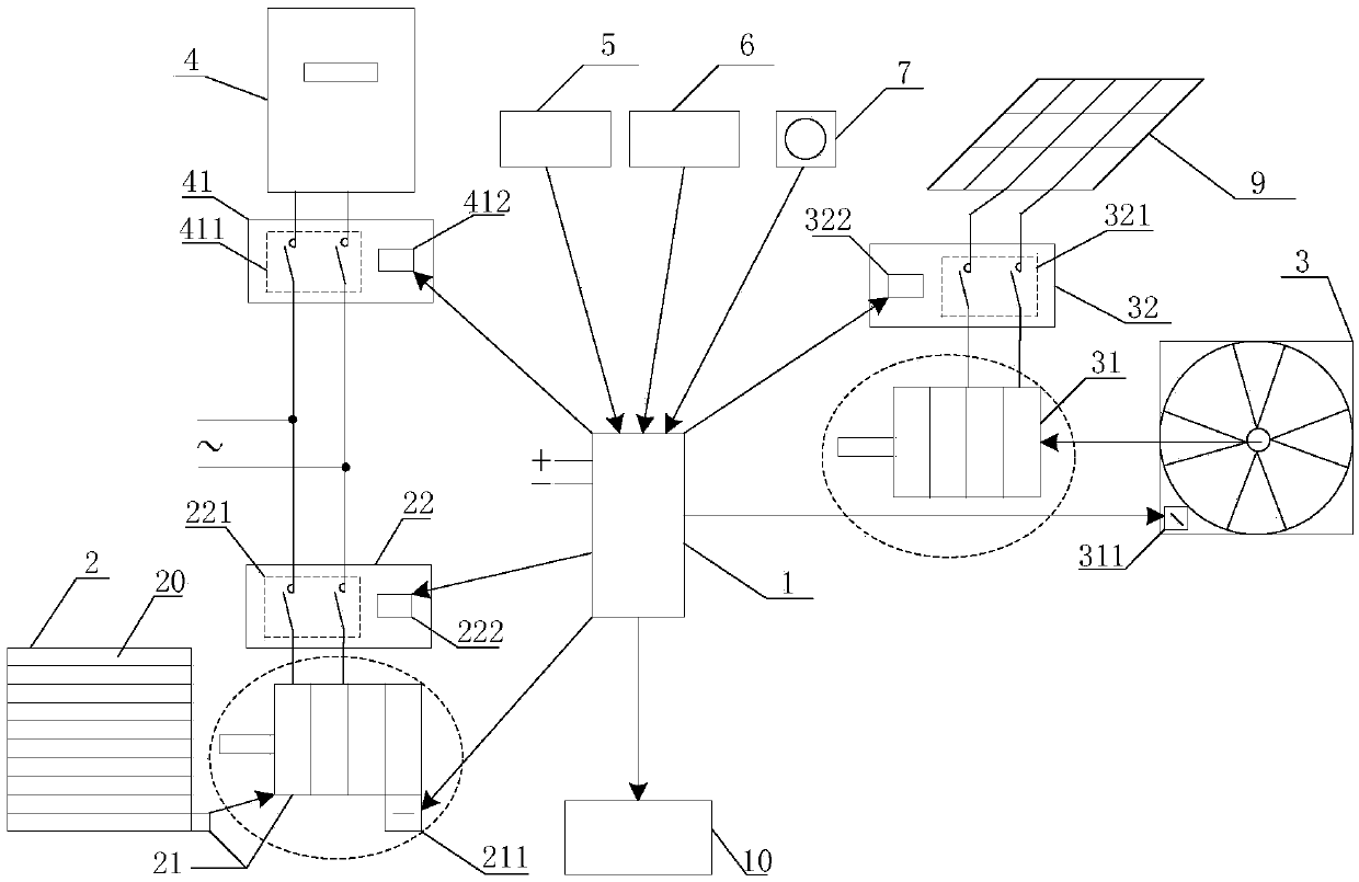
[0059] see figure 1 , is a functional block diagram of an embodiment of an elevator machine room temperature intelligent control system according to the present invention. Specifically, the elevator machine room temperature intelligent control system in this embodiment includes:

[0060] Controller 1, louver 2 with adjustable opening angle, main exhaust fan 3, air conditioner 4, louver motor 21 for adjusting the opening angle of louver 2, normally open louver motor control switch 22, for adjusting the speed gear of main exhaust fan 3 Main exhaust fan motor 31, normally closed main exhaust fan motor control switch 32, normally open air conditioner control switch 41, and the indoor temperature sensor 5 for detecting the indoor temperature in the elevator machine room and the outdoor temperature sensor for detecting the outdoor temperature outside the elevator machine room 6. Wherein, the louver 2 is installed at the bottom of any wall in the elevator machine room, and correspond...

Embodiment 2

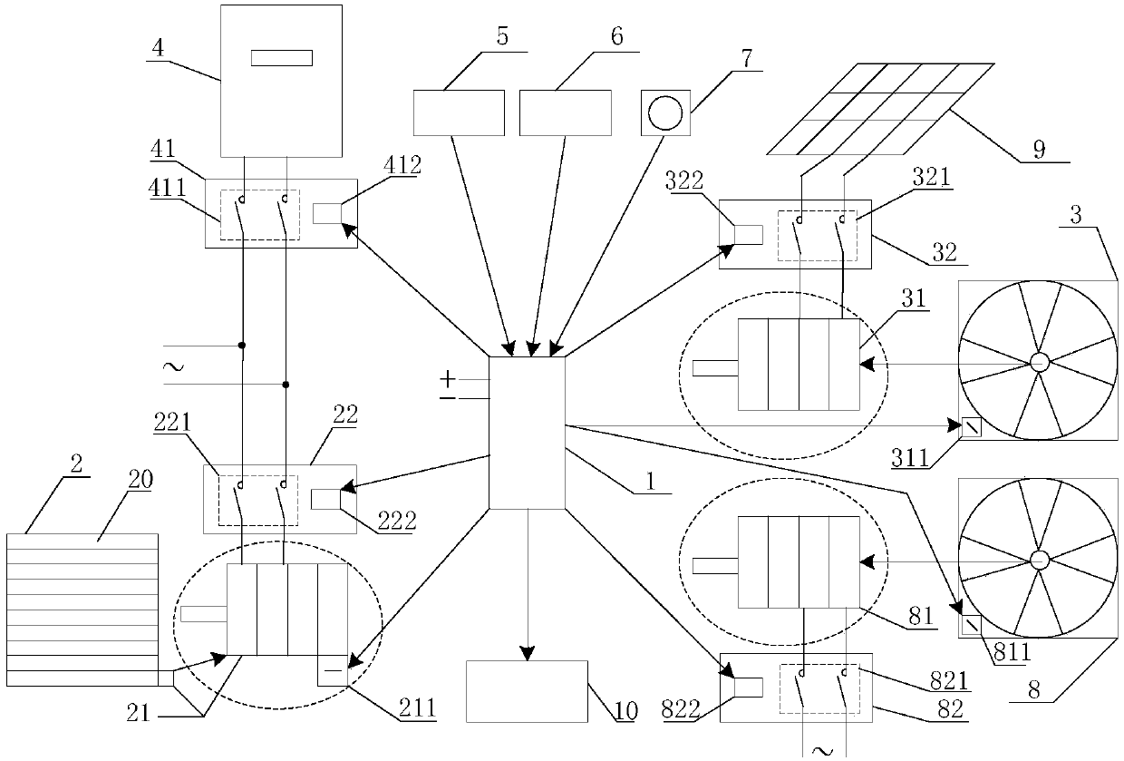
[0069] In order to effectively ensure that the common exhaust fan (ie, the main exhaust fan 3) and its related components can intelligently control the indoor temperature after failure, and also meet the requirements of energy saving, the present invention also provides an elevator machine room temperature intelligent control system, specifically, refer to figure 2 , in this embodiment, in addition to the various components in the above-mentioned first embodiment, it also includes a current sensor 7 for detecting the working current value of the main exhaust fan 3, and a backup exhaust fan 8 installed in parallel next to the main exhaust fan 3 for adjusting the The standby exhaust fan motor 81 with the rotation speed of the standby exhaust fan 8, and the standby exhaust fan motor control switch 82, wherein the standby exhaust fan motor control switch 82 is respectively connected with the controller 1 and the standby exhaust fan motor 81, and the standby exhaust fan motor 81 and...

Embodiment 3

[0077] Based on the elevator machine room temperature intelligent control system in the first embodiment, the present invention also provides an elevator machine room temperature intelligent control method, which will be described in detail below with reference to specific embodiments and accompanying drawings.

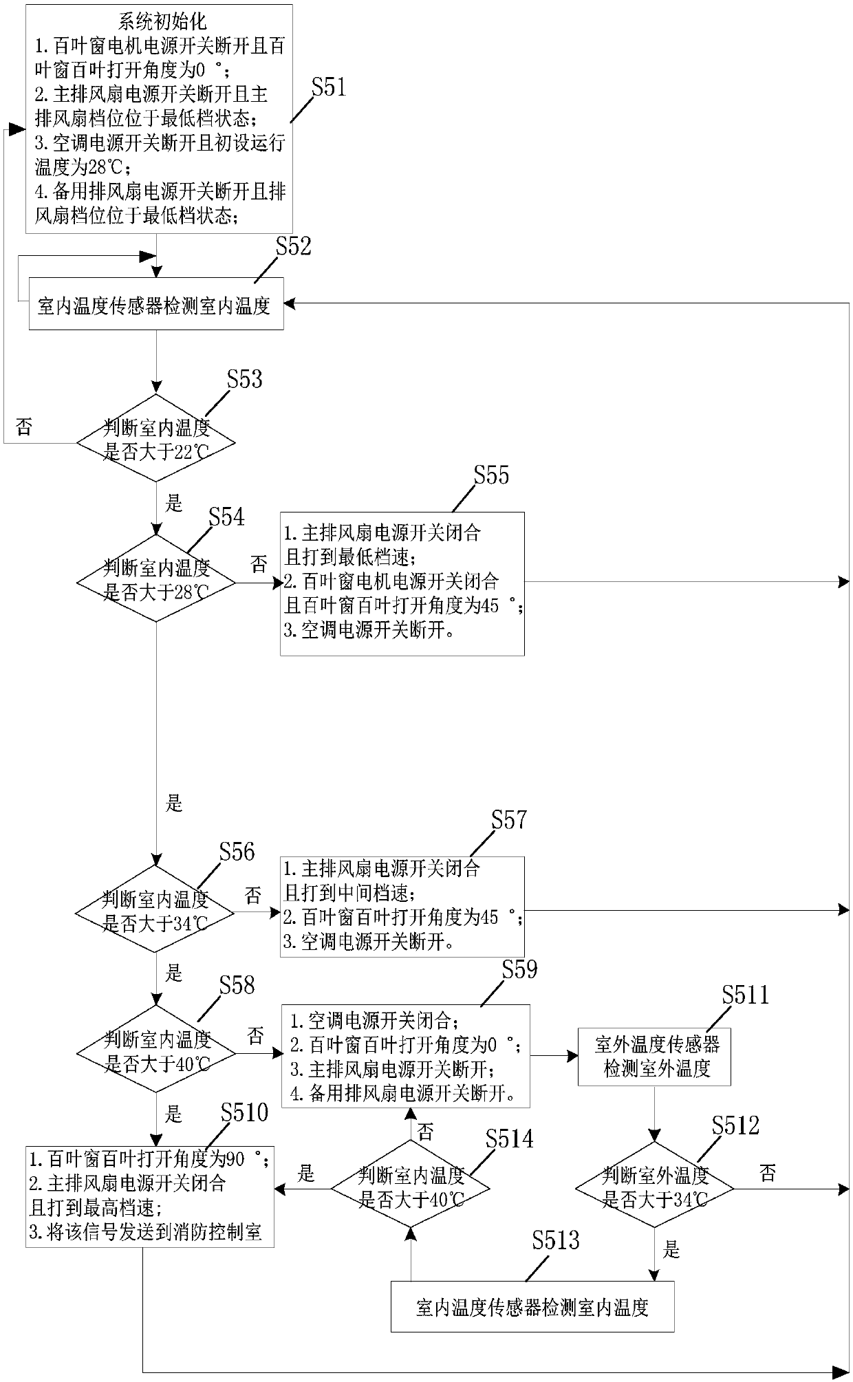
[0078] see image 3 , is a flowchart of an embodiment of an elevator machine room temperature intelligent control method of the present invention. Specifically, the elevator machine room temperature intelligent control method of this embodiment includes the steps:

[0079] S51, the elevator machine room temperature intelligent control system is initialized, and step S52 is executed.

[0080] In this embodiment, the initialization of the elevator machine room temperature intelligent control system means that when the indoor temperature is lower than 22°C, the elevator machine room temperature intelligent control system is installed and debugged, and when the debugging ...


PUM


Abstract

The invention discloses an elevator machine room temperature intelligent control system and method. According to the invention, an indoor temperature sensor is used for sensing the indoor temperatureand controlling the state of the corresponding ventilation cooling equipment according to the change of the indoor temperature; therefore, when the indoor temperature changes in different temperatureintervals, different ventilation and cooling measures are provided; corresponding ventilation and cooling measures can be automatically adjusted according to indoor temperature changes; manual intervention is not needed, the labor intensity of workers is reduced, reasonable ventilation and cooling measures are provided in different temperature intervals, namely, the temperature in the machine roomis intelligently controlled, equipment or device faults caused by the too high temperature in the elevator machine room are effectively avoided, and then accidental casualties of elevator passengersare effectively prevented; and on the other hand, the shutter, the main exhaust fan and the air conditioner are flexibly controlled by combining the indoor temperature and the external environment temperature, the operation states and relations of the shutter, the main exhaust fan and the air conditioner are adjusted, and energy saving is achieved while the temperature requirement in the machine room is met.

Description

technical field [0001] The invention relates to the technical field of heating and ventilation, and particularly relates to an elevator machine room temperature intelligent control system and a method thereof. Background technique [0002] At present, elevators are all machine rooms, and the main engine and control panel are placed in the machine room. Elevators are special equipment, corresponding safety measures must be implemented, and safety operating procedures must be strictly followed, otherwise there will be high hidden dangers. The elevator control cabinet in the elevator machine room will emit heat during operation. If the temperature of the elevator machine room is too high, the electronic board in the elevator control cabinet will work abnormally. In severe cases, the electronic board will be damaged and the service life of the equipment will be reduced. Therefore, in order to ensure the safe operation of the elevator, it is stipulated in the industry that the a...

Claims


Application Information

Patent Timeline
Patent Type & Authority Applications(China)
IPC IPC(8): H05K7/20
CPCH05K7/20136H05K7/20181
Inventor 于兵胡望社胡萍王锐刘雪潘令刚
Owner 中衡卓创(重庆)工程设计有限公司
Why Eureka
Try Eureka