Industrial conveyor chain with wear sensor

A sensor and conveyor chain technology, applied in the field of transmission chain, can solve problems such as no solution chain

Active Publication Date: 2020-06-12
DALOG DIAGNOSESYST GMBH
View PDF11 Cites 2 Cited by
  • Summary
  • Abstract
  • Description
  • Claims
  • Application Information

AI Technical Summary

Problems solved by technology

Despite the different designs for detecting link head wear of conveyor chains and predicting the service life

Method used


Image

  • Industrial conveyor chain with wear sensor
  • Industrial conveyor chain with wear sensor
  • Industrial conveyor chain with wear sensor

Examples


Embodiment Construction

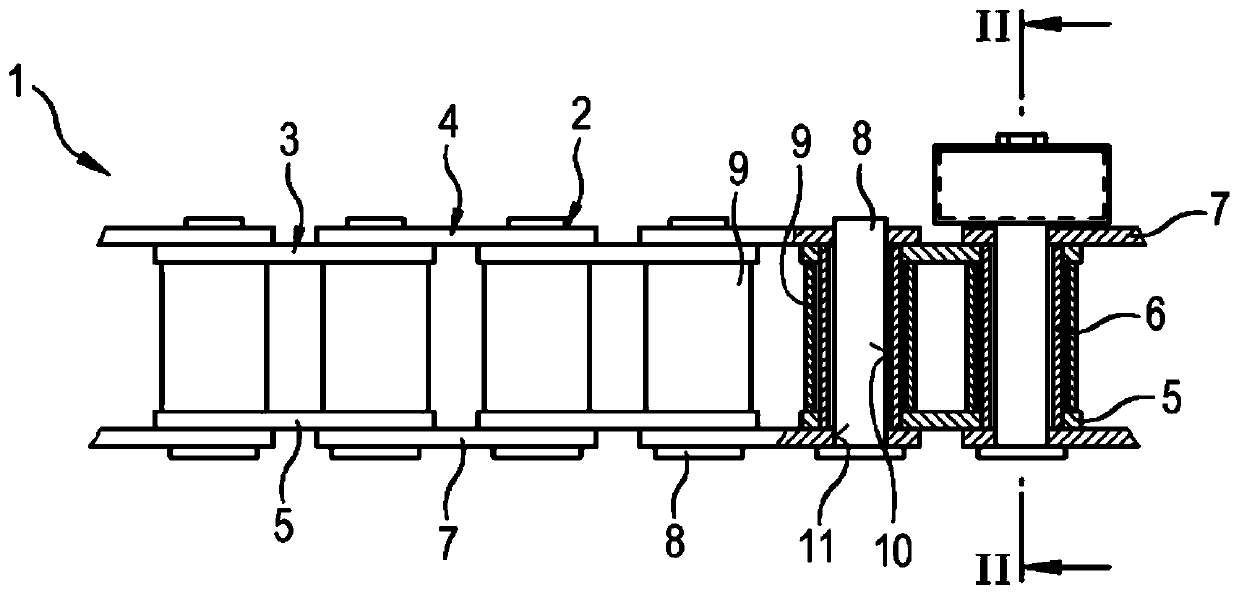
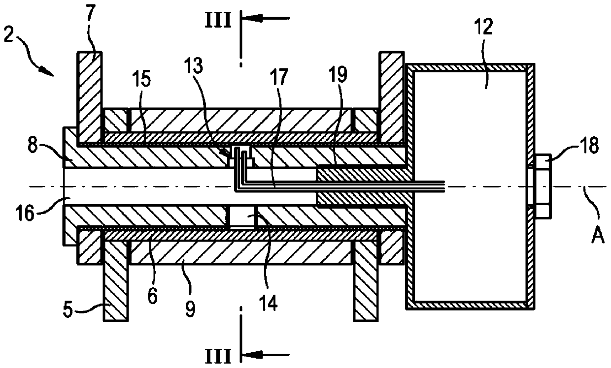
[0026] figure 1 The drive chain 1 shown in is realized as a roller chain with inner links 3 and outer links 4 connected via link joints 2, respectively. Each inner link 3 consists of two parallel inner plates 5 with two plate openings 11 and two joint sleeves 6 connecting the inner plates 5 to each other, wherein the joint sleeves 6 are perpendicular to the inner plates 5 and The connection sleeve 6 is fixedly connected to the inner plate 5 in the plate opening 11 , in particular by crimping. The outer chain link 4 consists of two parallel outer plates 7 which are connected to one another via two chain pins 8 , wherein the chain pins 8 are arranged rotatably in joint openings 10 of the joint sleeve 6 . The outer link 4 is movably fixed to the inner link 3 by means of chain pins 8 and is connected to the next inner link 3 by means of an outer plate 7 , wherein the outer plate 7 extends parallel to the inner plate 5 . Each chain pin 8 of the outer chain link 4 rotatably arran...


PUM

PropertyMeasurementUnit
Diameteraaaaaaaaaa

Abstract

The invention relates to a drive chain, in particular a conveyor chain for industrial systems, comprising a plurality of chain links, which are connected together via respective chain joints. A chainpin extends through a joint opening in the direction of a joint axis of the chain joint in order to form the chain joint. The conveyor chain also comprises a sensor for detecting chain wear. At leastone chain pin of the drive chain has a recess, and the sensor for detecting chain wear is arranged in the recess. The invention additionally relates to a chain pin and to a method for detecting chainwear of such a drive chain.

Description

technical field [0001] The invention relates to transmission chains, in particular conveyor chains for industrial equipment, having a plurality of chain links with sensors for chain wear detection, the chain links being connected to each other by link joints, wherein the chain pins are hinged at the link joints Axially extending through the joint opening to form a link joint. Furthermore, the invention relates to a chain pin for such a drive chain and a method for detecting chain wear of such a drive chain. Background technique [0002] Drive chains and related chain drives are important components for a wide range of applications in numerous fields of mechanical and industrial engineering, as well as in heavy industry, mining, surface mining, cement industry, passenger transport or the chemical industry. Due to the extreme conditions of use, such conveyor chains are sometimes subject to very high transport weights and other environmental influences in industrial plants, e....

Claims


Application Information

Patent Timeline
IPC IPC(8): B65G17/38B65G43/02F16G13/00G01N3/56
CPCB65G17/38B65G43/02B65G2203/0266B65G2207/40B65G2207/48F16D66/02F16G13/06
Inventor F·马斯切维克
Owner DALOG DIAGNOSESYST GMBH
Why Eureka
Try Eureka