
Assembled anatomical proximal femoral fracture intramedullary fixing device

A technology of proximal femur and fixation device, applied in the direction of internal fixator, fixator, internal bone synthesis, etc., can solve the problems of iatrogenic bursting of the lateral wall, difference in the effect of reduction and compression of the fracture end, and difficulty in placement, etc. Achieve the effects of reducing the possibility of iatrogenic burst, stabilizing fracture alignment, and promoting fracture healing

Pending Publication Date: 2020-06-16
TIANJIN WALKMAN BIOMATERIAL CO LTD
View PDF5 Cites 1 Cited by
  • Summary
  • Abstract
  • Description
  • Claims
  • Application Information

AI Technical Summary

Problems solved by technology

As far as the main nail is concerned, first of all, the shape design does not conform to the anatomical and morphological characteristics of the proximal femoral canal of the Chinese population, which makes the matching between the main nail and the proximal femoral canal poor, not only difficult to insert, but also easy to cause iatrogenic damage to the lateral wall. Second, when the existing main intramedullary nail is used in the internal fixation of proximal femoral fractures in the Chinese population, its proximal end often protrudes from the apex of the greater trochanter, causing irritation to the proximal soft tissue and resulting in long-term pain Discomfort occurs from time to time, which affects the life of the patient and the functional rehabilitation of the affected limb; third, the deflection angle of the main nail of the existing proximal femoral intramedullary nail is too large. Excessive force not only makes it difficult to insert, but also easily leads to local stress concentration; fourth, when the distal end of the main nail of the existing intramedullary nail passes through the anterior arch of the femur, the femoral medullary cavity of the anterior arch and the distal part of the main nail Stress blocking is easy to occur, which not only leads to difficulties in the insertion process of the main nail, but also causes the risk of stress fracture due to local stress concentration; fifth, the existing proximal femoral intramedullary nail lacks a smaller-diameter main nail, and some Patients with narrow medullary cavity (such as patients with abnormal bone metabolism and poliomyelitis) need internal fixation after proximal femur fracture. The choice of internal fixation device is very limited in some patients
In addition, the length of the femur varies greatly, which is related to many factors such as height and gender. The length of the main nail of the existing proximal femoral nail is limited.
As far as the existing proximal locking nails are concerned, the length of the helical blade and the locking part is single, and the differences between different types of fractures or different types of fractures of the same type are not considered, so it is difficult to achieve the best reduction and fixation effect. The effectiveness of internal fixation cannot be guaranteed
For example, the distance between the fracture end of the femoral neck base and the intertrochanteric fracture to the medial edge of the femoral head is different, and the length of the helical blade required is different. For individual internal fixation needs; for a fracture, it can be divided into various types and subtypes according to the number of fracture fragments and displacement degree
For fractures with different degrees of displacement, if proximal locking screws with the same length of the locking part are placed, the final reduction and compression effects of the fracture end will be quite different, and better recovery and prognosis cannot be achieved

Method used


Image

  • Assembled anatomical proximal femoral fracture intramedullary fixing device
  • Assembled anatomical proximal femoral fracture intramedullary fixing device
  • Assembled anatomical proximal femoral fracture intramedullary fixing device

Examples


Embodiment Construction

[0050] The technical solutions of the present invention will be described in further detail below with reference to the accompanying drawings and embodiments.

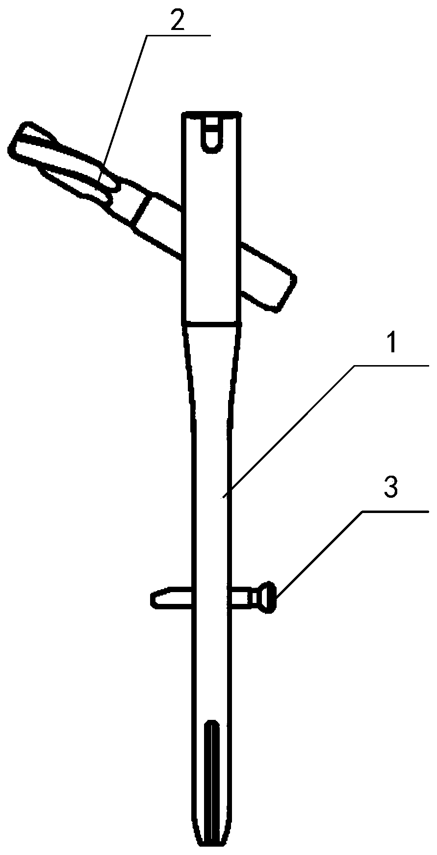
[0051] The proximal femoral locking nail provided by the embodiment of the present invention is applied to the fixation of the fracture site in the proximal femoral fracture operation. figure 1 A structural schematic diagram of an assembled anatomical proximal femoral fracture intramedullary fixation device provided by an embodiment of the present invention, as shown in figure 1 As shown, the assembled anatomical proximal femoral fracture intramedullary fixation device includes proximal intramedullary nail 1, proximal locking nail 2 and distal locking nail 3, proximal intramedullary nail 1, proximal locking nail 2 Cooperate with the distal locking nail 3 to fix the fracture site in the proximal femoral fracture operation. The structure and working process of the proximal intramedullary nail 1, the proximal locking nail...


PUM


Abstract

The embodiment of the invention relates to an assembled anatomical proximal femoral fracture intramedullary fixing device which comprises a proximal intramedullary nail, a proximal locking nail and adistal locking nail; the proximal intramedullary nail is of a rod-shaped structure and comprises a first fixing part, a transition part and a second fixing part; the proximal locking nail comprises atool bit, a connecting part and a sleeve; the shape of the proximal locking nail is matched with that of a second locking nail hole. The design of the appearances and the abduction angles of the firstfixing part and the transition part of the proximal femur intramedullary nail provided by the embodiment of the invention has extremely high matching degree with a proximal femur medullary cavity, different diameters and lengths can be selected, the intramedullary nail proximal part design avoids protruding out of the vertex of the greater trochanter, the distal forked structure design reduces the risk of stress fracture, and the proximal locking nail is provided with spiral blades with different lengths and central locking structures with different lengths, so that better restoration and more effective fixation between fracture ends are realized.

Description

technical field [0001] The invention relates to the field of orthopedic medical devices, in particular to a modular anatomical proximal femur fracture intramedullary fixation device. Background technique [0002] Proximal femoral fractures include femoral neck fractures, intertrochanteric fractures, and subtrochanteric fractures, accounting for about 7.3% of adult systemic fractures, and up to 23.8% of elderly fractures. With the aging of the global population, the incidence of proximal femoral fractures increases with age. According to reports, there are about 4.5 million cases of proximal femoral fractures in the elderly every year in the world, and the number of patients with proximal femoral fractures in the world is expected to increase to 21 million in the next 40 years, and the incidence of Asians accounts for about 50% of the global incidence. . The increasing treatment demands of proximal femoral fractures and the high quality of life of patients have become a cha...

Claims


Application Information

Patent Timeline
Patent Type & Authority Applications(China)
IPC IPC(8): A61B17/72A61B17/76
CPCA61B17/725A61B17/744A61B2017/564
Inventor 陈雁西强敏菲张坤赵国军黄朝朝吴欣然张庆杰
Owner TIANJIN WALKMAN BIOMATERIAL CO LTD
Learn More