Full-automatic shell welding production line

A welding production line, fully automatic technology, applied in welding equipment, welding equipment, auxiliary welding equipment, etc., can solve the problem of the compressor shell prone to shaking position, offset and other problems, and achieve the effect of easy brushing operation.

Pending Publication Date: 2020-06-16
浙江加西贝拉科技服务股份有限公司
View PDF0 Cites 5 Cited by
  • Summary
  • Abstract
  • Description
  • Claims
  • Application Information

AI Technical Summary

Problems solved by technology

[0004] Aiming at the problems raised by the background technology, the present invention designs a fully automatic shell welding production line, which solves the problem that the compressor shell is prone to shake or position shift during the brushing process

Method used


Image

  • Full-automatic shell welding production line
  • Full-automatic shell welding production line
  • Full-automatic shell welding production line

Examples


Embodiment 1

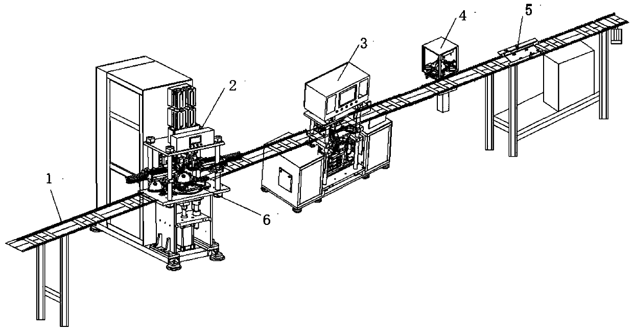
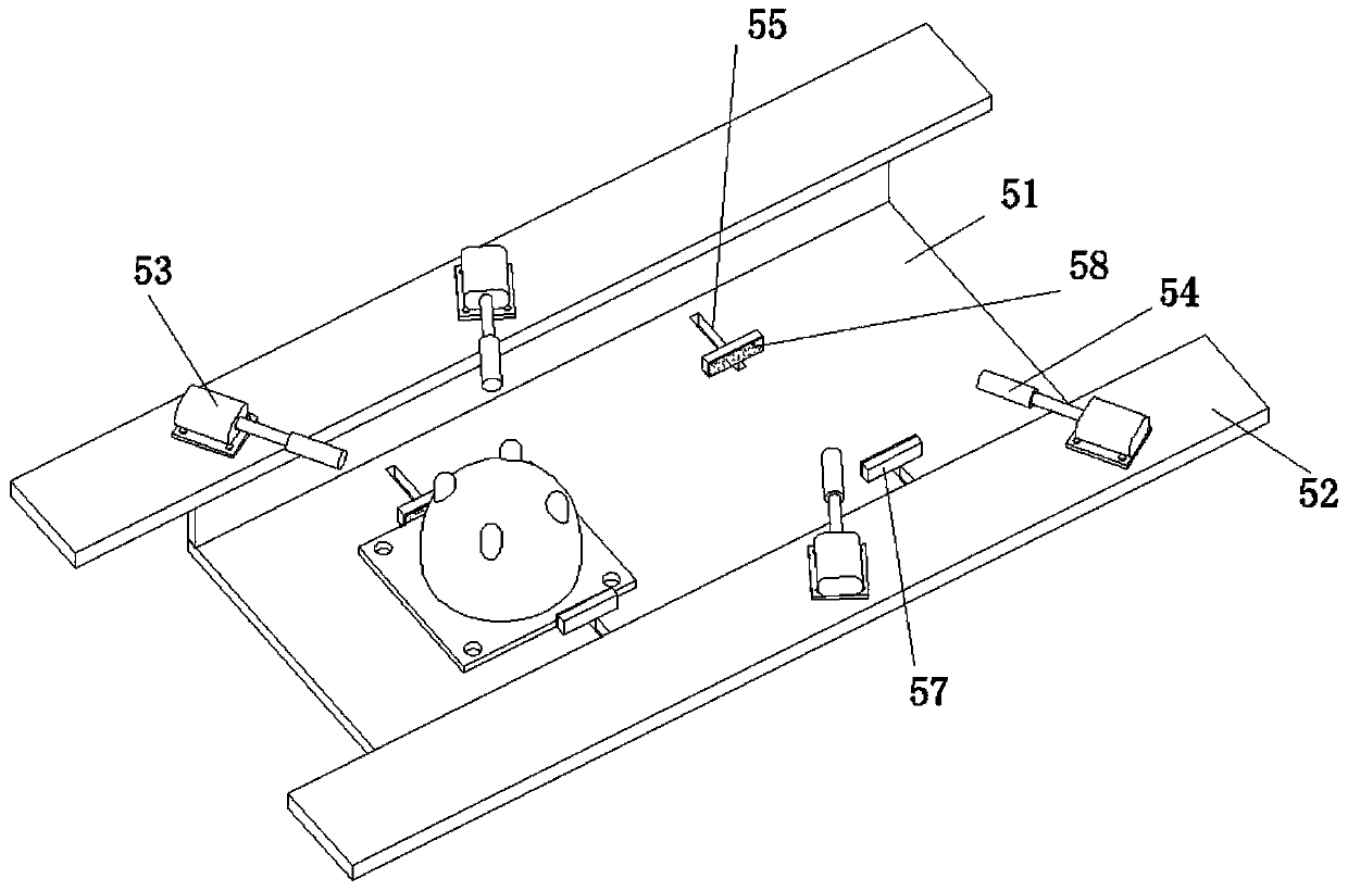
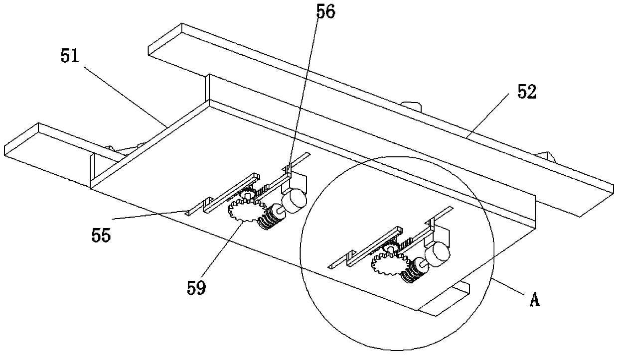
[0038] A fully automatic shell welding production line, such as Figure 1-3 As shown, it includes a conveyor line body 1, foot plate welding equipment 2, convex nail welding equipment 3 and position detection equipment 4 connected in sequence from left to right. The position detection device 4 is provided with a brushing mechanism 5, and the transmission line body 1 adopt 08B-U2 stainless steel chain and standard aluminum alloy profiles, and the upper and lower chains are in the form of pallets, the brushing mechanism 5 includes a brushing bottom plate 51, a brushing side plate 52 and a brushing motor 53, two brushing side plates 52 They are respectively fixedly mounted on the front and rear ends of the brushing base plate 51, and the upper end surfaces of the two brushing base plates 51 are fixedly installed with two brushing motors 53 with two stations, and the output of each brushing motor 53 Each end is provided with a brushing shaft 54, and the upper surface of the brushi...

Embodiment 2

[0043] Embodiment 2 is a further improvement on the basis of Embodiment 1, mainly for the purpose of simplifying the structure and having a better clamping and fixing effect, which will be described in detail below.

[0044] A fully automatic shell welding production line, such as figure 1 with Figure 5 As shown, it includes foot plate welding equipment 2, convex nail welding equipment 3 and position detection equipment 4 connected in sequence from left to right by the transmission line body 1. The position detection equipment 4 is equipped with a brushing mechanism 5, and the transmission line body 1 adopts 08B -U2 stainless steel chain and standard aluminum alloy profiles, and the upper and lower chains are in the form of pallets. The brushing mechanism 5 includes a brushing bottom plate 51, a brushing side plate 52 and a brushing motor 53. The two brushing side plates 52 are respectively Fixedly installed on the front and rear ends of the brushing base plate 51, the upper...


PUM


Abstract

The invention relates to the technical field of shell welding production, in particular to a full automatic shell welding production line comprises foot plate welding equipment, protruding nail welding equipment and position detecting equipment, wherein the foot plate welding equipment, the protruding nail welding equipment and the position detecting equipment are sequentially connected from leftto right of a conveying line body. A burnishing mechanism is arranged in the position detecting equipment. The burnishing mechanism comprises burnishing bottom plates, a burnishing side plate and burnishing motors. The burnishing motors of two stations are fixedly installed on the upper end faces of the two burnishing bottom plates correspondingly through fasteners. Two sliding grooves are formedin the upper surfaces of the burnishing bottom plates. Sliding blocks are installed in the two sliding grooves in a sliding manner. Clamping blocks are installed at the top ends of the sliding blocks.Anti-skid pads are installed on the outer walls of the clamping blocks. Clamping drive mechanisms are arranged at the bottom ends of the sliding blocks. According to the production line, in the burnishing process, a compressor shell is clamped conveniently, the compressor shell does not shake or deviate, oxide skin, rusting mark and burrs generated after machining on the surface of the compressorshell are cleared off beneficially, and the unglazed forge face appearance is obtained.

Description

technical field [0001] The invention relates to the technical field of shell welding production, in particular to an automatic shell welding production line. Background technique [0002] The compressor is regarded as the heart of the refrigeration system, and the special term that best expresses the characteristics of the compressor is called "vapor pump". The actual responsibility of the compressor is to increase the pressure and increase the suction pressure state to the discharge pressure state. It inhales low-temperature and low-pressure refrigerant gas from the suction pipe, drives the piston to compress it through the operation of the motor, and discharges high-temperature and high-pressure refrigerant gas to the exhaust pipe to provide power for the refrigeration cycle. [0003] In order to meet the needs of vibration isolation and noise reduction, when the refrigeration compressor is installed on the bottom plate of a household or commercial refrigerator or freezer...

Claims


Application Information

Patent Timeline
Patent Type & Authority Applications(China)
IPC IPC(8): B23K31/02B23K37/00B24B9/04B24B27/00B24B41/00B24B41/06
CPCB23K31/02B23K37/00B24B9/04B24B27/0076B24B41/005B24B41/06
Inventor 胡根林宋哲民邵加军范淳纯浦建峰温磊
Owner 浙江加西贝拉科技服务股份有限公司
Why Eureka
Try Eureka