Movable magnetic seat drill and bench drill with replaceable electric drill assembly and no guide rail

A technology of drilling without guide rails and magnetic base, which is applied in the direction of large fixed members, other manufacturing equipment/tools, metal processing machinery parts, etc., can solve the problems of work efficiency and work content interference, and achieve high tapping and drilling capabilities, Easy to move and wide application

Inactive Publication Date: 2020-06-16
企能科技(广州)有限公司
View PDF0 Cites 0 Cited by
  • Summary
  • Abstract
  • Description
  • Claims
  • Application Information

AI Technical Summary

Problems solved by technology

[0006] The purpose of the present invention is to solve: the existing magnetic base drill needs to be connected with electric wires to work, and the electric wires will cause certain interference to work efficiency and work content, and are potentially dangerous;

Method used


Image

  • Movable magnetic seat drill and bench drill with replaceable electric drill assembly and no guide rail
  • Movable magnetic seat drill and bench drill with replaceable electric drill assembly and no guide rail
  • Movable magnetic seat drill and bench drill with replaceable electric drill assembly and no guide rail

Examples


Embodiment 1

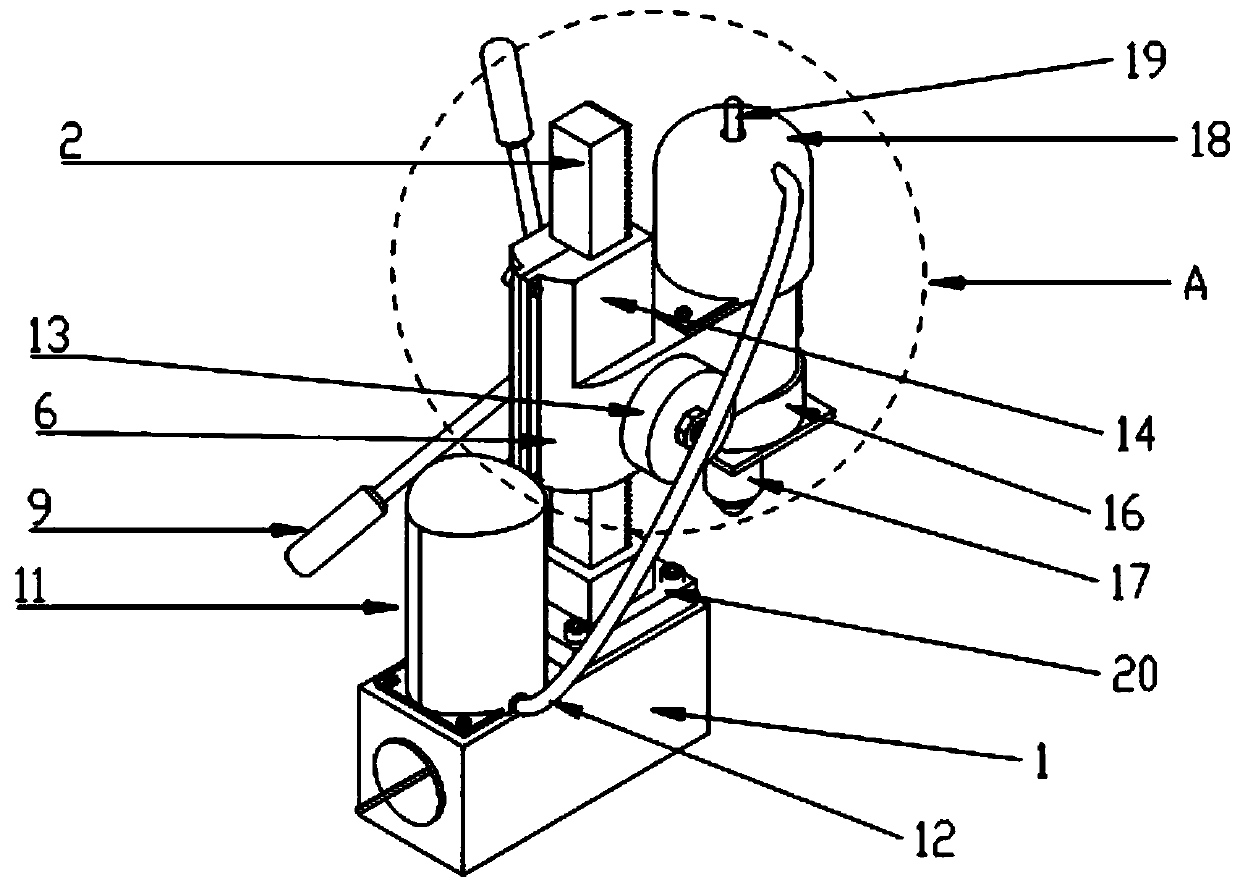
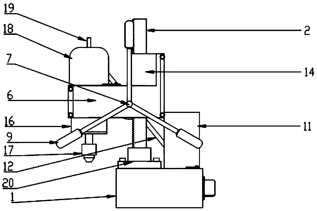
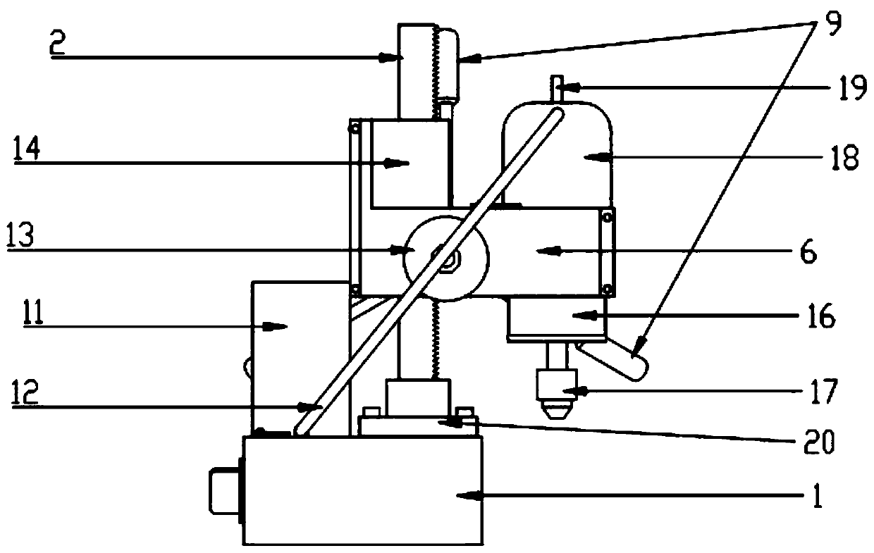
[0048] Such as Figure 1 to Figure 12 As shown, the present invention can replace the electric drill assembly and the movable magnetic base drill without guide rail includes a magnetic base 1, and a rack 2 and a battery 11 are fixedly installed on the magnetic base 1, and the battery 11 can also be installed on the magnetic base. other positions on the side of 1; the installation of the rack 2 can be directly fixedly connected with the magnetic base 1, and the preferred implementation mode in this embodiment is: first install a rack base 20 fixedly connected with it on the magnetic base 1, and the teeth The fixed connection between the bar base 20 and the magnetic base 1 can be welded or bolted, and then the rack 2 is installed on the rack base 20, so that the fixed connection between the rack 2 and the magnetic base 1 is more stable;

[0049]It also includes a machine head clamp 6, which is a whole. In this embodiment, the preferred method is: at least two equal half bodies t...

Embodiment 2

[0052] Depend on Figure 13 As shown, the present invention can replace the electric drill assembly and the movable bench drill without guide rail, its embodiment is to replace the magnetic base 1 with the bottom plate 21 on the basis of embodiment 1, so that the magnetic base drill can be converted into a bench drill.


PUM


Abstract

The invention relates to the field of machine tools and metal machining tools, in particular to a movable magnetic seat drill and bench drill with a replaceable electric drill assembly and no guide rail. The movable magnetic seat drill with the replaceable electric drill assembly and no guide rail aims to solve the problems that an existing magnetic seat drill needs to be connected with an electric wire to be capable of working; parts are many, and the cost is high; and the existing magnetic seat drill is narrow in application range and cannot be suitable for working environments with different requirements on torque. The movable magnetic seat drill with the replaceable electric drill assembly and no guide rail comprises a magnetic seat and a machine head clamp, wherein a rack fixedly connected with the magnetic seat is mounted on the magnetic seat, a first mounting hole and a second mounting hole penetrating through the main body of the machine head clamp up and down, and a third mounting hole horizontally penetrating through the main body of the machine head clamp are formed in the machine head clamp, the rack is located in the first mounting hole to be slidably connected with the first mounting hole, a power output device fixedly connected with the second mounting hole is mounted in the second mounting hole, the movable magnetic seat drill with the replaceable electric drillassembly and no guide rail further comprises a control shaft in clearance fit with the third mounting hole formed in the third mounting hole, gear teeth surrounding the main body of the control shaftare mounted in the middle of the main body of the control shaft, the control shaft is in meshing connection with the rack, and a manipulating piece fixedly connected with the control shaft is mountedat one end of the control shaft.

Description

technical field [0001] The invention relates to the field of machine tools and metal processing tools, in particular to a movable magnetic base drill and a bench drill with replaceable electric drill assemblies and no guide rails. Background technique [0002] Magnetic base drill is also called magnetic drill and magnet drill. After electrification, the changing current at the bottom of the magnetic drill generates a magnetic field, which is adsorbed on the steel structure, and then the magnetic drill motor drives the drill at high speed to realize drilling of the steel structure. [0003] The emergence of magnetic drills is an urgent need for magnetic drills in people's field practice work: first of all, when people want to work in the field and at high altitudes, they need to drill and tap holes as accurately as indoor machine tools, but general hand tools cannot be accurate. ; Next is to vertical steel structure punching and tapping, and when needing inverted punching a...

Claims


Application Information

Patent Timeline
Patent Type & Authority Applications(China)
IPC IPC(8): B23P23/02B23Q1/26B23Q11/00
CPCB23P23/02B23Q1/26B23Q11/00
Inventor 曾卫民
Owner 企能科技(广州)有限公司
Why Eureka
Try Eureka