Arm quick-release structure of plant protection unmanned aerial vehicle and usage method
A technology for plant protection drones and arms, applied in the field of drones, can solve the problems affecting the convenience of drone use, large storage or transportation space, inconvenient disassembly and reinstallation, etc., to achieve simple structure and avoid The effect of falling off and ensuring stability
- Summary
- Abstract
- Description
- Claims
- Application Information
AI Technical Summary
Problems solved by technology
Method used
Image
Examples
Embodiment 1
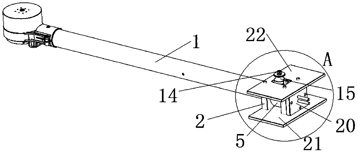
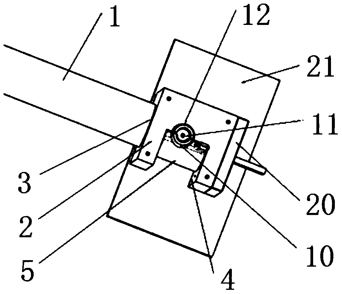
[0028] Such as figure 1 , 5 As shown in and 6, a quick-release structure of the arm of a plant protection drone includes a machine arm 1 and a machine arm base 2, and the machine arm base 2 is provided with a connection hole 3 that is plugged with the machine arm 1, and the connection hole 3 is connected to the machine arm 1. The machine arm 1 is coaxially arranged, the machine arm seat 2 on the side of the connection hole 3 is provided with a rotation groove 4, and a limit block 5 is rotated in the rotation groove 4, and a side of the limit block 5 close to the connection hole 3 is provided with a The assembly groove 6 attached to the side wall of the machine arm 1, the block 7 is fixed in the assembly groove 6, the side wall of the machine arm 1 is provided with a groove 8 matching with the block 7, the limit block 5 and the arm seat 2 An openable locking piece is arranged between them.
[0029] The usage method of this embodiment: Insert one end of the machine arm 1 into ...
Embodiment 2
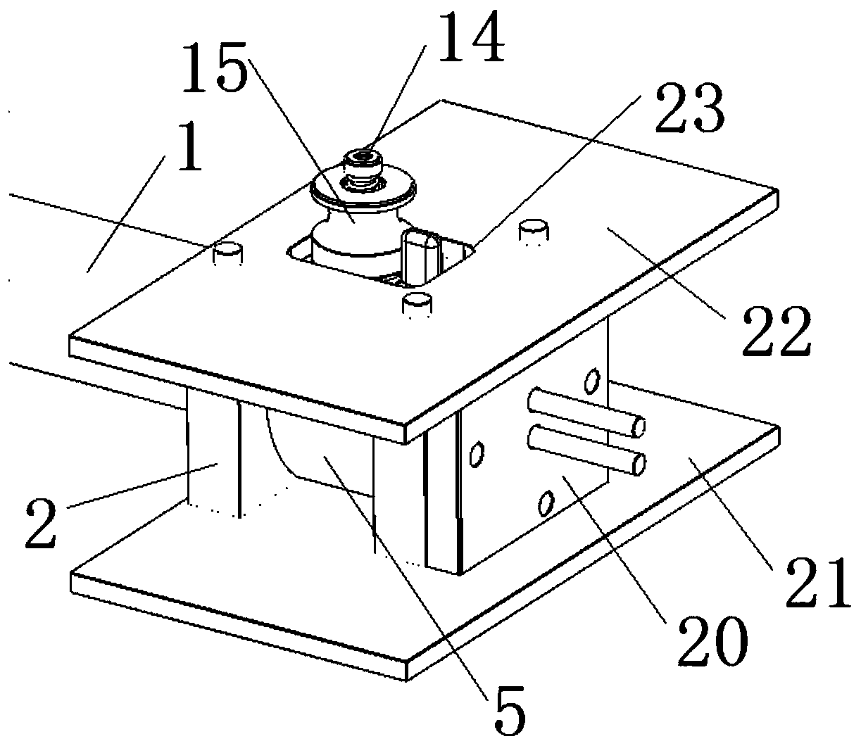
[0031] This embodiment is basically the same as Embodiment 1, except that the lower end of the limit block 5 is connected to the machine arm base 2 in rotation through plug screws 9, the plug screws 9 are arranged along the axial direction of the machine arm 1, and the limit block The upper end of 5 is provided with the first arc ring 10, is provided with threaded hole 11 in the second arc ring 12, and the upper end of machine arm base 2 is provided with the second arc ring 12 that cooperates with the first arc ring 10, lock The fastener includes a spring 13, a locking screw 14 and a handle 15. The lower end of the locking screw 14 slides through the spring 13 and the handle 15 in turn, and is fixedly connected with the threaded hole 11. The lower end of the handle 15 is provided with a limiting groove 16, and the handle 15 is set on the outside of the first arc-shaped ring 10 and the second arc-shaped ring 12 through the limit groove 16, and the locking of the handle 15 is rea...
Embodiment 3
[0033] This embodiment is basically the same as embodiment one and / or two, the difference is: as Figure 2-7 As shown, the end of the machine arm 1 close to the machine arm base 2 is provided with the machine arm end terminal board 17, and the machine arm terminal terminal board 17 is provided with the machine arm terminal positive pole incoming line 18 and the machine arm terminal negative pole for powering the machine arm 1 motor. The incoming line 19, the end of the machine arm base 2 away from the machine arm 1 is provided with a fuselage terminal terminal board 20 that cooperates with the machine arm terminal terminal board 17, and the fuselage terminal terminal board 20 is fixed on the fuselage of the drone. The terminal terminal board 20 is connected with the negative outlet of the fuselage terminal and the positive outlet of the fuselage. After the machine arm 1 is inserted into the connection hole 3, the terminal board 17 at the machine arm end is offset against the t...
PUM
 Abstract
Description
Claims
Application Information
 - R&D
- Intellectual Property
- Life Sciences
- Materials
- Tech Scout
- Unparalleled Data Quality
- Higher Quality Content
- 60% Fewer Hallucinations
Browse by: Latest US Patents, China's latest patents, Technical Efficacy Thesaurus, Application Domain, Technology Topic, Popular Technical Reports.
© 2025 PatSnap. All rights reserved.Legal|Privacy policy|Modern Slavery Act Transparency Statement|Sitemap|About US| Contact US: help@patsnap.com


