A preparation process of composite porous carbon film and capacitor

A preparation process, porous carbon technology, applied in the preparation/purification of carbon, hybrid capacitor electrodes, ceramic products, etc., can solve the problems of increased internal resistance, increased processing difficulty, etc., to reduce internal resistance, improve volume utilization, reduce The effect of thickness

Active Publication Date: 2021-06-04
南京动量材料科技有限公司
View PDF1 Cites 0 Cited by
  • Summary
  • Abstract
  • Description
  • Claims
  • Application Information

AI Technical Summary

Problems solved by technology

However, this NCS membrane material needs to be adhered to an additional current collector plate to collect current, which will inevitably increase processing difficulty and lead to negative effects such as increased internal resistance.

Method used


Image

  • A preparation process of composite porous carbon film and capacitor
  • A preparation process of composite porous carbon film and capacitor
  • A preparation process of composite porous carbon film and capacitor

Examples


Embodiment 1

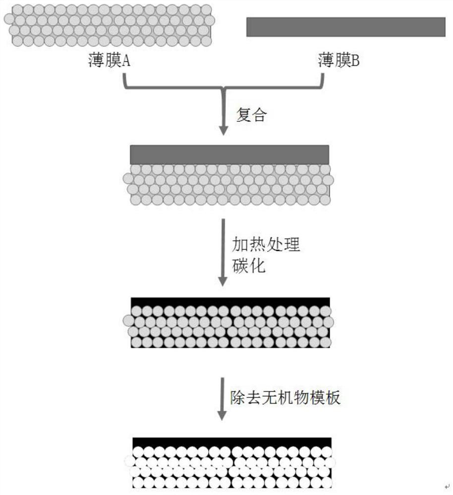
[0062] Such as figure 1 As shown, the specific process of the preparation process of the present embodiment is as follows:

[0063] (1) Preparation of film A

[0064] 50 g of a 10 wt% aqueous solution of polyvinyl alcohol (PVA, 86-89% hydrolyzed), 2 g of 1,3-propanediol (PD), and 2 g of n-butanol were added to the milling jar. After ball milling for 1 hour, the aqueous phase suspension containing 5g of 50nm silica sol and 2g of PD was added into the ball mill jar. After ball milling for 2 hours, the slurry (mixed suspension) was separated and defoamed. The slurry was coated onto a glass substrate by casting with a gap of 0.10 mm between the doctor blade and the substrate. After the water evaporates, the film is peeled off from the substrate to obtain a fresh film A containing SiO2 / PVA / PD.

[0065] (2) Preparation of film B

[0066] 2 g of mesophase pitch (MP) and 4 g of n-butanol were added to the mill jar. After ball milling for 1 hour, 2 g of 1,3-propanediol (PD) and 5...

Embodiment 2

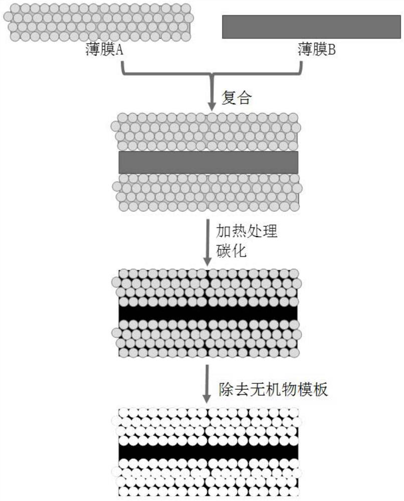
[0072] The specific process of the preparation process of this embodiment can be found in figure 2, the preparation process of film A and film B is exactly the same as that of Example 1, the only difference is that when compounding in step (3), the two are laminated together in the mode of A-B-A to form a composite film. In this way, after the same step (4) as in Example 1, a self-supporting double-sided nanoporous film (d-NCS-50, "50" represents the size 50nm of the corresponding silica sol particles) .

Embodiment 3

[0074] (1) Preparation of film A

[0075] 50 g of 5 wt % polymethyl acrylate (PMMA) in chloroform, 5 g of dibutyl phthalate (DBP) and 2 g of n-butanol were added to the ball mill jar. After ball milling for 1 hour, add 5g of 500nm alumina powder into the ball mill jar. After ball milling for 2 hours, the slurry (mixed suspension) was separated and defoamed. The slurry was coated onto a glass substrate by casting with a gap of 0.10 mm between the doctor blade and the substrate. After the solvent evaporated, the film was peeled off from the substrate to obtain a fresh sheet containing Al 2 o 3 Film A of / PMMA / DBP.

[0076] (2) Preparation of film B

[0077] 2 g of mesophase pitch (MP) and 4 g of chloroform were added to the mill jar. After ball milling for 1 hour, 2 g of DBP and 50 g of 5 wt% PMMA / chloroform solution were added to the ball mill jar. After ball milling for another 2 hours, the slurry (mixed suspension) was separated and defoamed. The slurry was coated ont...


PUM

PropertyMeasurementUnit
particle sizeaaaaaaaaaa
thicknessaaaaaaaaaa
particle sizeaaaaaaaaaa

Abstract

The invention discloses a preparation process of a composite porous carbon film and a capacitor using the carbon film. The composite porous carbon film has at least one porous carbon layer, and preferably also has a dense carbon layer. The porous carbon layer has a high specific surface area, which realizes the large specific capacity of the capacitor, and has three-dimensionally connected pores, which greatly reduces the ion transmission resistance and improves its electrical conductivity; the dense carbon layer has the function of blocking fluid, which can prevent gas or liquid from passing through , when used as a unipolar plate or bipolar plate in a capacitor, the dense carbon layer can prevent the electrolyte from entering the other side from one side, preventing the performance of the capacitor from deteriorating or being damaged. The electrode plate (especially the bipolar plate) can be made very thin by using the composite porous carbon film, which saves equipment space, reduces the internal resistance of the capacitor, improves energy efficiency, and has good economic and social benefits.

Description

technical field [0001] The invention relates to a carbon film, in particular to a preparation process of a composite porous carbon film, which can be applied to capacitors; it belongs to the technical field of new materials. Background technique [0002] Nanostructured carbon materials have many advantages such as low specific gravity, good conductivity, high specific surface area, and easy surface modification, so they have been extensively and in-depth researched, and have been widely used in many popular industries such as water treatment, fuel cells, and sensors. application. At present, most carbon materials exist in the form of powder. Since the orientation of individual nanoporous carbon particles is easy to change, it will affect the material transport through the nanopores, so the reproducibility of product performance is poor, which greatly limits the use of carbon materials. scope of application. [0003] With the development of technology, some new technologies...

Claims


Application Information

Patent Timeline
Patent Type & Authority Patents(China)
IPC IPC(8): C01B32/05H01G11/24H01G11/34
CPCC04B35/52C04B35/522C04B35/622C04B38/04C04B2235/48C04B2235/656C04B2235/6562C04B2235/6567H01G11/24H01G11/34C04B38/0054C04B38/0051
Inventor 力小安嵇从民张珂
Owner 南京动量材料科技有限公司
Why Eureka
Try Eureka