
Electronic endoscope for medical imaging

An electronic endoscope, medical imaging technology, applied in endoscopy, medical science, application and other directions, can solve the problems of increasing the pain and discomfort of patients, unable to meet the needs of doctors for diagnosis, unable to focus effectively, etc. The effect of improving clarity and recognition, increasing lubricity, and increasing work efficiency

Pending Publication Date: 2020-06-19
杨丹
View PDF20 Cites 0 Cited by
  • Summary
  • Abstract
  • Description
  • Claims
  • Application Information

AI Technical Summary

Problems solved by technology

[0006] In order to make up for the shortcomings of the existing technology, when the existing electronic endoscope uses the lighting lens to irradiate the human body organs, due to the fixed focal length of the objective lens, when it penetrates into different positions of the human body, it cannot focus effectively, which eventually leads to the imaging clarity of the CCD Poor, unable to meet the doctor's diagnosis needs, need to use the endoscope to enter the human body for observation many times, the efficiency is relatively low, and it also increases the pain and discomfort of the patient during diagnosis. The invention proposes a Electronic endoscope for medical imaging

Method used


Image

  • Electronic endoscope for medical imaging
  • Electronic endoscope for medical imaging
  • Electronic endoscope for medical imaging

Examples


Embodiment approach

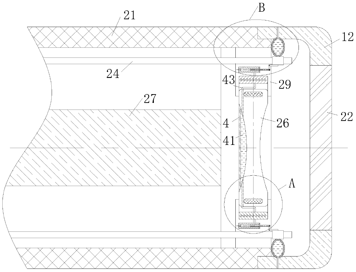
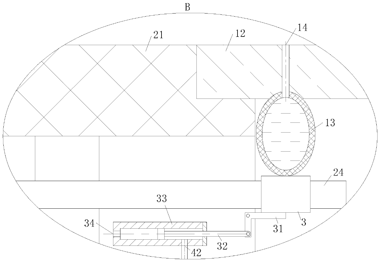
[0024] As an embodiment of the present invention, the end of the optical fiber 24 close to the lens 22 is covered with a steering sleeve 3, and the side of the outer circumference of the steering sleeve 3 close to the objective lens 26 is fixedly connected with an L-shaped swing rod 31, and the corner of the swing rod 31 is connected to the The mirror body 21 is hinged; the end of the swing rod 31 away from the steering sleeve 3 is hinged with a flexible telescopic rod 32, and the end of the telescopic rod 32 away from the swing rod 31 is fixedly connected with a piston. The mirror body 21 is fixedly connected; the oil inlet hole 34 provided at the bottom of the cylinder 33 communicates with the control device through a pipeline, and the cylinder 33 is filled with liquid for driving the piston; the sliding of the piston is controlled by the control device, and then the optical fiber 24 is controlled. The angle of the head further increases the working efficiency of the endoscop...


PUM


Abstract

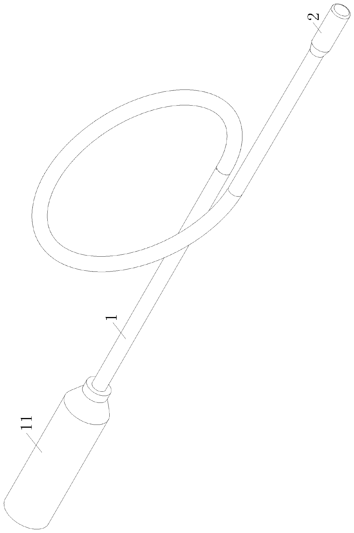
The invention belongs to the technical field of medical imaging equipment, and particularly relates to an electronic endoscope for medical imaging. The electronic endoscope includes an insertion tube;the two ends of the insertion tube are fixedly connected to a handheld part and an endoscope lens respectively; the endoscope lens is connected to a control imaging display device through wires and optical fibers which are arranged in the handheld part and the insertion tube; the endoscope lens comprises a tubular endoscope body, one end of the endoscope body is fixedly connected to the insertiontube, and the other end of the endoscope body is fixedly connected to a lens; an annular mounting seat is fixedly connected into the endoscope body, and a group of optical fibers for illumination areuniformly distributed on the periphery of the mounting seat; a flexible objective lens is arranged in an annular groove formed in the inner periphery of the mounting base, and a CCD video line is arranged at one end, away from the lens, of the objective lens; an annular cavity is formed in a position, close to the outer edge, of the objective lens, and the annular cavity is filled with magnetofluid; and an electromagnet surrounding the periphery of the objective lens is arranged at the bottom of the annular groove, and the electromagnet is connected to the control imaging display device through a wire. The focal length of the objective lens is controlled through the electromagnet, and the definition and the identification degree of the endoscope are improved.

Description

technical field [0001] The invention belongs to the technical field of medical imaging equipment, in particular to an electronic endoscope for medical imaging. Background technique [0002] Endoscope is a testing instrument that integrates traditional optics, ergonomics, precision machinery, modern electronics, mathematics, and software. One has image sensors, optical lenses, light source lighting, mechanical devices, etc., and it can enter the stomach through the mouth or enter the body through other natural channels. The endoscope can be used to see lesions that cannot be seen on X-rays, so it is very useful for doctors. For example, with the help of an endoscope, doctors can observe ulcers or tumors in the stomach and formulate the best treatment plan accordingly. [0003] Electronic endoscope is a medical electronic optical instrument that can be directly inserted into the body cavity or organ cavity for diagnosis. It uses extremely small electronic imaging components ...

Claims


Application Information

Patent Timeline
IPC IPC(8): A61B1/05A61B1/07A61B1/12A61B1/00
CPCA61B1/05A61B1/07A61B1/00131A61B1/128A61B1/00082
Inventor 杨丹李鑫
Owner 杨丹
Learn More