Automatic rubberizing equipment, method for tearing rubber ring body paper and automatic rubberizing method
A glue and equipment technology, applied in chemical instruments and methods, mechanical equipment, cleaning methods and utensils, etc., can solve the problems of unstable glue effect and low efficiency, save manpower, ensure uniform quality and glue efficiency high effect
- Summary
- Abstract
- Description
- Claims
- Application Information
AI Technical Summary
Problems solved by technology
Method used
Image

Examples
Embodiment 1
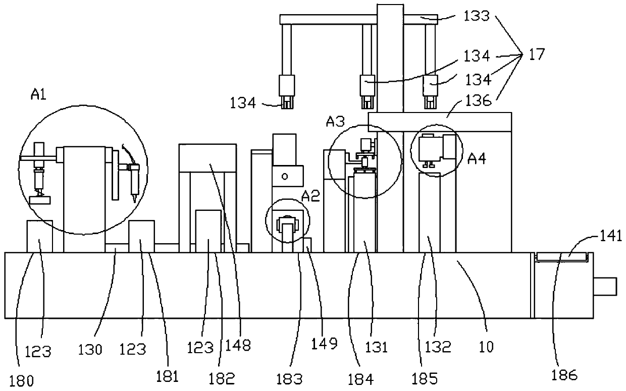
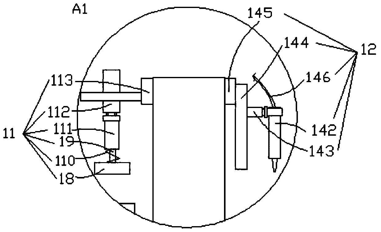
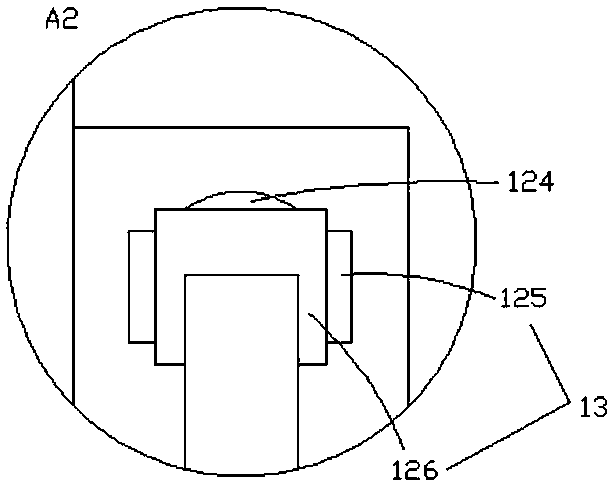
[0044] The embodiment of the present invention provides a kind of automatic gluing equipment, such as Figure 1-Figure 8 , Figure 10-Figure 13 As shown, it includes a workbench 10; the workbench 10 is provided with a cleaning station 180, a gluing station 181, a glue curing station 182, a 180° turning station 183, a bonding station 184, and a pressing station 185. , and the finished product blanking station 186; the workbench 10 is also provided with a cleaning assembly 11, a gluing assembly 12, a glue curing assembly, a material turning assembly 13, a bottom paper assembly 14, and a pressing assembly 15, which will be connected with the first three The three sets of rotating fan blades 2 corresponding to the stations are all moved back to the first material moving assembly 16 of one station, and the three groups of rotating fan blades 2 corresponding to the fourth to sixth stations are all moved back by one station The second material moving component 17;
[0045] The clea...
Embodiment 2
[0077] The embodiment of the present invention provides an automatic gluing equipment, which is the same as Embodiment 1 and will not be described in detail. The difference is:
[0078] Such as Figure 9 As shown, the automatic gluing equipment also includes a first apron box 153 located below the backing paper assembly 14, a receiving plate 154 for stacking the aprons in the first apron box 153, and driving the receiving plate 154 to move along the Z axis The second cylinder 155; the first rubber ring box 153 and the second cylinder 155 are fixed with the workbench 10; the material receiving surface of the receiving plate 154 is an inner concave surface matching with the rotating fan blade 2; the first rubber ring box 153 is provided with Avoid the escape channel of the movable end of the second cylinder 155;
[0079] The workbench 10 is provided with the first bonding seat 156 corresponding to the bonding station 184; the first bonding seat 156 includes a fixed frame 157 fi...
Embodiment 3
[0091] The embodiment of the present invention provides a method for tearing the backing paper of the rubber ring, based on the second embodiment, the method includes the following steps:
[0092] Step S101: The motor drives the vertical plate to rotate, and the suction plate moves toward the first apron box.
[0093] Step S102: The second cylinder drives the receiving plate up, and the rubber ring on the top layer is attached to the suction plate.
[0094] Step S103: The first air pump draws air, and the top rubber ring is adsorbed onto the suction pan.
[0095] Step S104: The motor drives the vertical plate to rotate, the apron backing paper on the suction tray is stuck by the double-sided adhesive on the cam, and continues to rotate, the apron backing paper is completely torn off, and the suction tray is covered with the adhesive that has no backing paper. Circle back to the gluing station and wait for gluing.
[0096] Step S105: The completely torn apron backing paper st...
PUM
 Abstract
Description
Claims
Application Information
 - R&D
- Intellectual Property
- Life Sciences
- Materials
- Tech Scout
- Unparalleled Data Quality
- Higher Quality Content
- 60% Fewer Hallucinations
Browse by: Latest US Patents, China's latest patents, Technical Efficacy Thesaurus, Application Domain, Technology Topic, Popular Technical Reports.
© 2025 PatSnap. All rights reserved.Legal|Privacy policy|Modern Slavery Act Transparency Statement|Sitemap|About US| Contact US: help@patsnap.com