Electronic waste recycling treatment device and treatment method

A technology of electronic waste and recycling, which is applied in grain processing, chemical instruments and methods, wet separation, etc., can solve the problems of reducing metal recovery efficiency, environmental hazards, and increasing waste disposal costs, and achieves improved drying efficiency and enhanced drying effect of effect

Inactive Publication Date: 2020-06-19
高琦彬
View PDF0 Cites 8 Cited by
  • Summary
  • Abstract
  • Description
  • Claims
  • Application Information

AI Technical Summary

Problems solved by technology

Electronic waste contains a very high proportion of heavy metals and precious metals. If it is directly used as landfill, it will not only cause great harm to the environment, but also waste a large amount of valuable metals
At present, e-waste is mainly classified and recycled after manual sorting, but the efficiency of manual sorting is very low, and in the process of manual sorting, it is not possible to fully separate metals from closely bonded plastic products, and After manual sorting, a part

Method used


Image

  • Electronic waste recycling treatment device and treatment method
  • Electronic waste recycling treatment device and treatment method

Examples


Embodiment 1

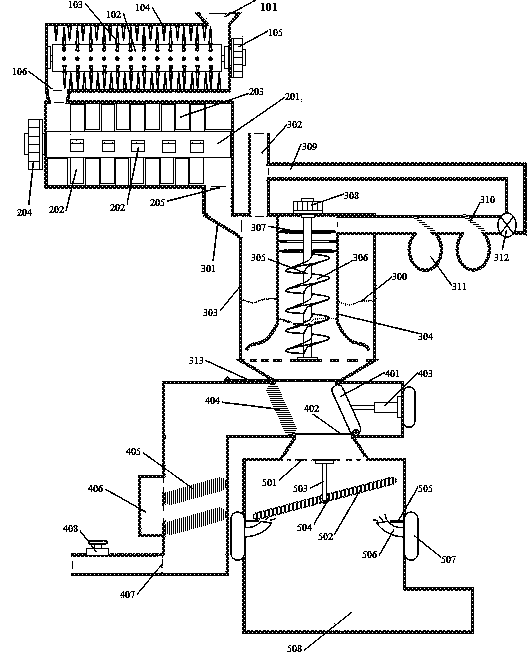
[0033] Further explanation in conjunction with accompanying drawings: Figure 1 to Figure 2 It is an e-waste recycling and processing device according to this embodiment, which includes a primary crushing chamber, a fine crushing chamber, a density separation device, a pressing water removal component and a drying chamber. in figure 1 It is an internal view, that is, the internal structure diagram after partial shell removal.

[0034] Such as figure 1 As shown, the primary crushing chamber includes a primary crushing chamber casing, an electronic waste inlet 101, a primary crushing shaft 102, a shaft crushing cone 103, a wall crushing cone 104, a primary crushing drive motor 105, and a primary crushing chamber discharge port 106; figure 1 The shell of the primary crushing chamber shown is a horizontal cylindrical structure with both ends closed, the entrance of the electronic waste is set on the top of the shell of the primary crushing chamber, and the primary crushing shaft...

Embodiment 2

[0046] A method for recycling and processing electronic waste, the processing method uses the electronic waste recycling and processing device of embodiment 1, specifically comprising the following steps:

[0047] (1) Put the electronic waste into the primary crushing chamber through the entrance of the electronic waste, start the primary crushing drive motor, the electronic waste is discharged into the fine crushing chamber through the inlet of the fine crushing chamber after primary crushing in the primary crushing chamber, and start The fine crushing drive motor finely crushes the electronic waste, and then discharges it through the discharge port of the fine crushing chamber. The maximum particle size of the crushed material discharged through the outlet of the fine crushing cavity is 18mm.

[0048] (2) The material crushed by the fine crushing cavity is discharged into the separation outer cavity through the inlet of the separation outer cavity and is the outside of the sep...


PUM


Abstract

The invention relates to an electronic waste recycling treatment device and a treatment method using the device to recycle electronic waste. The device comprises a primary crushing cavity, a fine crushing cavity, a density separating device, an extruding water-removing part and a drying room. The density separating device is arranged, and a single spiral blade can rotate, so that water and crushedmaterials are integrally lifted and then are released, and therefore, materials with density much greater than that of water are separated from materials with density close to that of water or smaller than that of water, and solid-solution separation is realized through an extrusion and filtration way; and a drying plate with a special structure is arranged, so that the solid materials are storedafter being dried, and therefore, relative fine recycling efficiency of electronic waste is greatly improved.

Description

technical field [0001] The invention relates to the field of electronic waste treatment and recovery, in particular to an electronic waste recovery treatment device and treatment method. Background technique [0002] E-waste mainly contains a large amount of metals, semi-metals and plastics, rubber and a small amount of inorganic non-metallic materials. Electronic waste contains a very high proportion of heavy metals and precious metals. If it is directly used as landfill, it will not only cause great harm to the environment, but also waste a large amount of valuable metals. At present, e-waste is mainly classified and recycled after manual sorting, but the efficiency of manual sorting is very low, and in the process of manual sorting, it is not possible to fully separate metals from closely bonded plastic products, and After manual sorting, a part of cheap metals and plastics or inorganic non-metallic materials that are tightly combined with them will be landfilled or inci...

Claims


Application Information

Patent Timeline
IPC IPC(8): B09B3/00B09B5/00B02C18/14B02C18/18B03B5/28B30B9/06F26B21/00F26B25/00
CPCB09B5/00B03B5/28B30B9/062F26B21/00F26B25/00B02C18/14B02C18/18B02C18/0092B09B3/40
Inventor 不公告发明人
Owner 高琦彬
Why Eureka
Try Eureka