Long nozzle structure for free injecting flow of tundish and argon blowing smelting method

A smelting method and tundish technology, applied in the direction of casting molten material containers, manufacturing tools, metal processing equipment, etc., can solve the problems of high energy consumption and maintenance costs, and achieve easy maintenance of equipment, saving energy consumption of argon filling, and simple equipment Effect

Active Publication Date: 2020-06-19
NORTHEASTERN UNIV
View PDF7 Cites 3 Cited by
  • Summary
  • Abstract
  • Description
  • Claims
  • Application Information

AI Technical Summary

Problems solved by technology

The improvement of the shroud in the existing technology is basically focused on reducing the impact on the tundish, preventing the pouring splash, improving the safety of the pouring, etc., and seldom designed from the aspect of improving the cleanliness of the molten steel; while the argon blowing smelting The process needs to continuously provide a source of argon gas with a certain pressure to the molten steel, resulting in high energy consumption and maintenance costs

Method used


Image

  • Long nozzle structure for free injecting flow of tundish and argon blowing smelting method
  • Long nozzle structure for free injecting flow of tundish and argon blowing smelting method

Examples


Embodiment Construction

[0034]In order to better explain the present invention and facilitate understanding, the present invention will be described in detail below through specific embodiments in conjunction with the accompanying drawings.

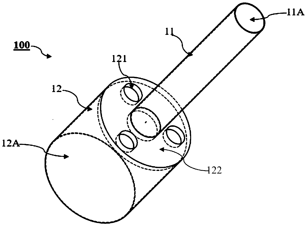
[0035] Such as figure 1 As shown in the figure, it is a schematic structural view of the tundish free-flow shroud structure in a preferred embodiment of the present invention. figure 1 It is a tundish free injection shroud structure 100, which includes: an upper pipe section 11 and a second pipe 12, inside which respectively form a pipe hole 11A and a pipe hole 12A, and the pipe hole 11A and the pipe hole 12A are in communication. Wherein, the lower pipe section 12 is connected below the upper pipe section 11 , and the inner diameter of the pipe hole 12A is larger than the inner diameter of the pipe hole 11A. Preferably, the inner diameter of the tube hole 12A is 2-4 times, in this embodiment, 3 times, the inner diameter of the tube hole 11A. Wherein, the uppe...


PUM

PropertyMeasurementUnit
heightaaaaaaaaaa

Abstract

The invention relates to a long nozzle structure for free injecting flow of a tundish. The long nozzle structure comprises an upper pipe section and a lower pipe section, pipe holes are formed in theupper pipe section and the lower pipe section respectively, and the pipe hole in the upper pipe section communicates with the pipe hole in the lower pipe section; inner diameter of the pipe hole in the lower pipe section is larger than that of the pipe hole in the upper pipe section, an air hole is formed in the lower pipe section and communicates with the pipe hole in the lower pipe section. A traditional steel ladle long nozzle is divided into the thinner upper pipe section and the thicker lower pipe section, the inner top surface of the lower pipe section is higher than molten steel for a certain distance, and an argon absorbing space is formed between the lower pipe section and the molten steel liquid level. The molten steel forms free injecting flow under the gravity after flowing outfrom the upper pipe section, argon in the argon absorbing space is absorbed into the molten steel to form tiny argon bubbles, and the argon absorbing space is supplemented with argon automatically bythe aid of negative pressure. The phenomenon of bubble enlarging caused by the non-wetting condition in the argon blowing process of the nozzle can be inhibited, the problem of blockage of the air hole in the argon blowing process can be solved, and the structure is easy to maintain and can realize deep purification of the molten steel under the condition of lower cost.

Description

technical field [0001] The invention relates to the field of iron and steel metallurgy, in particular to a continuous casting tundish free injection shroud structure applied to clean steel smelting and an argon blowing smelting method using the shroud. Background technique [0002] At this stage, the steel industry is facing the dilemma of "overcapacity at the low end and insufficient production capacity at the high end". Under the increasingly stringent environmental pressure, improving the performance of steel and adjusting the product structure are the only way for the sustainable and healthy development of steel enterprises. At present, the number and maximum size of inclusions contained in some high value-added steel products should meet strict requirements. Therefore, minimizing the size and quantity of inclusions in steel and realizing the smelting of clean steel with high efficiency and low cost is an important way to improve product quality and increase the profita...

Claims


Application Information

Patent Timeline
Patent Type & Authority Applications(China)
IPC IPC(8): B22D41/58C21C7/072C21C7/076
CPCB22D41/58C21C7/072C21C7/076Y02P10/20
Inventor 常胜刘铮周吉安邹宗树邵磊曲迎霞
Owner NORTHEASTERN UNIV
Why Eureka
Try Eureka