Numerical control lathe

A CNC lathe and lathe technology, applied in the field of CNC lathes, can solve the problems of nut pair translation obstruction, dirt, bolt looseness, etc., and achieve the effect of smooth and unimpeded translation, preventing scaling and avoiding clogging

Active Publication Date: 2020-06-19
邵阳永腾金属制品有限公司
View PDF8 Cites 4 Cited by
  • Summary
  • Abstract
  • Description
  • Claims
  • Application Information

AI Technical Summary

Problems solved by technology

[0003] The screw is an important component of the CNC lathe. The movement of the tool holder is realized by the cooperation of the screw and the nut pair. However, the existing screw is exposed, and the screw has a thread groove. When the workpiece is processed, cutting chips will be generated, and the cutting chips will also fall into the thread groove, which will hinder the translation of the nut pair. When idle, the dust and impurities in the air will also fall into the thread groove. , will make dust and impurities adhere to the thread groove, forming dirt, which is not conducive to the translation of the nut pair, and it is inconvenient to clean and descale the screw rod;
[0004] In addition, the blades are simply fixed by bolts. Since the blades are subjected to external processing forces and resonance forces during processing, the bolts will loosen, which in turn will cause the blades to loosen, which is not conducive to the processing of the workpiece.

Method used


Image

  • Numerical control lathe
  • Numerical control lathe
  • Numerical control lathe

Examples


Embodiment 1

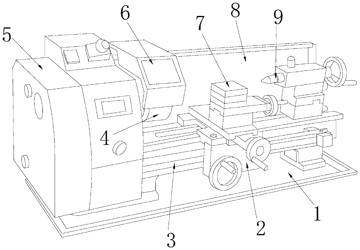
[0043] see figure 1 , the present invention provides a technical solution for a numerically controlled lathe: please refer to Figure 1-3 , the present invention provides a technical solution for a CNC lathe: its structure includes a base 1, a moving assembly 2, a screw assembly 3, a chuck 4, a lathe body 5, a dust cover 6, a lathe tool rest 7, a guard plate 8, Tailstock jacking mechanism 9, described base 1 is provided with lathe body 5, and described lathe body 5 is fixed with guard plate 8, and described lathe body 5 is equipped with chuck 4, and above described chuck 4 is provided with dust-proof Cover 6, one side of the chuck 4 is provided with a tailstock jacking mechanism 9, and the tailstock jacking mechanism 9 is movably connected with the lathe body 5, and the lathe body 5 is provided with a screw assembly 3, and the wire The rod assembly 3 is connected with a mobile assembly 2, and the movable assembly 2 is fixed with a liftable lathe tool rest 7;

[0044] see ...

Embodiment 2

[0052] see figure 1 , the present invention provides a technical solution for a CNC lathe: its structure includes a base 1, a moving assembly 2, a screw assembly 3, a chuck 4, a lathe body 5, a dust cover 6, a lathe tool rest 7, a guard plate 8, Tailstock jacking mechanism 9, described base 1 is provided with lathe body 5, and described lathe body 5 is fixed with guard plate 8, and described lathe body 5 is equipped with chuck 4, and above described chuck 4 is provided with dust-proof Cover 6, one side of the chuck 4 is provided with a tailstock jacking mechanism 9, and the tailstock jacking mechanism 9 is movably connected with the lathe body 5, and the lathe body 5 is provided with a screw assembly 3, and the wire The rod assembly 3 is connected with a mobile assembly 2, and the movable assembly 2 is fixed with a liftable lathe tool rest 7;

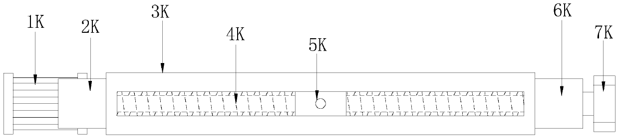
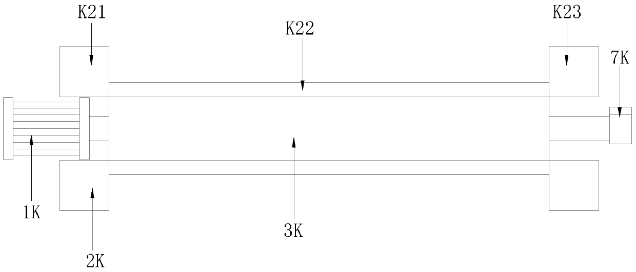
[0053] see figure 2 , Figure 4 , the screw assembly 3 includes a micro motor 1K, No. 1 dust-proof device 2K, dust-proof box 3K, ...


PUM


Abstract

The invention discloses a numerical control lathe. The numerical control lathe comprises a base, a moving module, a lead screw module, a chuck, a lathe body, a dustproof cover, a lathe cutter frame, aprotecting plate, and a tail frame top car mechanism; the lathe body is arranged on the base; and the protecting plate is fixed on the lathe body. Compared with the prior art, the numerical control lathe has the beneficial effects that: the lead screw module adopts a novel structure configuration; a lead screw can be hidden to prevent exposing outside, so that chips generated by lathe processingand external dust are effectively prevented from falling into a thread groove of the lead screw, blockage of the thread groove of the lead screw is prevented, scaling of the thread groove is prevented, translation of the moving module is smooth, and the lead screw has no need to be cleaned and descaled; and the blade mounting base adopts a novel structure configuration, implements multiple fixation to effectively prevent looseness of bolts and blades, so that processing of processed parts by the blades is facilitated.

Description

technical field [0001] The invention relates to the technical field of numerically controlled lathes, in particular to a numerically controlled lathe. Background technique [0002] CNC lathe is one of the most widely used CNC machine tools at present. It is mainly used for cutting the inner and outer cylindrical surfaces of shaft parts or disk parts, the inner and outer conical surfaces of arbitrary cone angles, the complex rotary inner and outer curved surfaces, cylinders, and conical threads, etc., and can perform grooving, drilling, reaming, and reaming. Holes and borings etc. [0003] The screw is an important component of the CNC lathe. The movement of the tool holder is realized by the cooperation of the screw and the nut pair. However, the existing screw is exposed, and the screw has a thread groove. When the workpiece is processed, cutting chips will be generated, and the cutting chips will also fall into the thread groove, which will hinder the translation of the ...

Claims


Application Information

Patent Timeline
Patent Type & Authority Applications(China)
IPC IPC(8): B23B7/14B23B29/04B23Q11/08
CPCB23B7/12B23B29/04B23Q11/08
Inventor 李正本
Owner 邵阳永腾金属制品有限公司
Why Eureka
Try Eureka